my question is: is better RLC multimeter the clio empirical measure?
Hi diypass:
Yes, a high quality LCR multimeter will always be better than any audio measurement system for such applications. If you can afford it, I've found this to be excellent for the price:
Keysight U1733C LCR Meter
If you want to learn more about cable capacitance and its affect on audio frequencies, you might want to read the following. This paper also includes a link to an Excel spreadsheet cable capacitance calculator that you may find helpful.
Microphone Cabling Considerations with CLIO-FW and CLIO Pocket
Last edited:
Hi. I understood the LCR precision (limit) of PC apps depends on their input impedance.
I saw recommendations in some whitepapers to have at least 1 megaohm to compete with semi-pro (100-400$) meters.
That was tested with other software using the instrument input of soundcards.
I understand the looping from clio uses either the 150 ohm output or its 64kohm input rerouted internally...?? Either way its not much not precise and rather amateur level.
Hi Joshcpct:
The thing that has held my interest in audio for almost 40 years at this point is how difficult it is. One can go as deep as they wish into the rabbit hole of audio physics and never hit bottom.")
CLIO and CLIO Pocket use one of the most sophisticated and most accurate inductance and capacitance measurement algorithms on the market for L and C values relevant to loudspeaker design. The CLIO method is also quite accurate for larger and smaller values up to a point, but extremely small and large value reactive components require special equipment like the U1733C to get correct answers.
Details
The CLIO Pocket hardware has an unbalanced 150Ω output and 64kΩ input, CLIO 12 (and earlier FireWire units) have balanced 660Ω outputs and 128kΩ inputs.
The process used by almost all LCR meters including CLIO is to measure the impedance of an L or C component at a given frequency. This impedance is also known as the reactance of the component and the frequency used for the measurement is used with the measured reactance to calculate L or C. An explanation including the math is in the following video:
CLIO Pocket Impedance Measurement - Capacitors & Inductors
What very few people understand is that for a given reactive component, the frequency selected to make the measurement dictates the ideal source impedance to use for the most accurate result. Stated in reverse; with a given source impedance (such as with CLIO and every other audio measurement hardware I know of), and a given inductor or capacitor value, there is an ideal frequency at which to make the measurement for the most accurate result.
The CLIO systems take the latter approach and automatically select the measurement frequency based on the reactance of the device under test (DUT). This is a very powerful feature of the CLIO systems that no other system offers to my knowledge. This is explained in detail here:
Electrical Impedance Measurements with CLIO
Nevertheless, due to the fixed hardware impedances, the CLIO auto frequency selection algorithm is most useful for the range of reactances typical in loudspeaker applications. For ranges outside this domain, such as cable capacitances in the pF (10^-12) range that are being discussed in this thread, you MUST change the source impedance of the measurement instrument to achieve correct results.
The Keysight U1733C deals with this requirement by changing its output impedance as needed to achieve good S/N required for accurate reactance measurement. This is why you need a high quality dedicated LCR meter if you want to be able to measure reactances outside the loudspeaker realm that we normally deal with. See attached U1733C capacitance measurement specifications.

The thing that has held my interest in audio for almost 40 years at this point is how difficult it is. One can go as deep as they wish into the rabbit hole of audio physics and never hit bottom.
CLIO and CLIO Pocket use one of the most sophisticated and most accurate inductance and capacitance measurement algorithms on the market for L and C values relevant to loudspeaker design. The CLIO method is also quite accurate for larger and smaller values up to a point, but extremely small and large value reactive components require special equipment like the U1733C to get correct answers.
Details
The CLIO Pocket hardware has an unbalanced 150Ω output and 64kΩ input, CLIO 12 (and earlier FireWire units) have balanced 660Ω outputs and 128kΩ inputs.
The process used by almost all LCR meters including CLIO is to measure the impedance of an L or C component at a given frequency. This impedance is also known as the reactance of the component and the frequency used for the measurement is used with the measured reactance to calculate L or C. An explanation including the math is in the following video:
CLIO Pocket Impedance Measurement - Capacitors & Inductors
What very few people understand is that for a given reactive component, the frequency selected to make the measurement dictates the ideal source impedance to use for the most accurate result. Stated in reverse; with a given source impedance (such as with CLIO and every other audio measurement hardware I know of), and a given inductor or capacitor value, there is an ideal frequency at which to make the measurement for the most accurate result.
The CLIO systems take the latter approach and automatically select the measurement frequency based on the reactance of the device under test (DUT). This is a very powerful feature of the CLIO systems that no other system offers to my knowledge. This is explained in detail here:
Electrical Impedance Measurements with CLIO
Nevertheless, due to the fixed hardware impedances, the CLIO auto frequency selection algorithm is most useful for the range of reactances typical in loudspeaker applications. For ranges outside this domain, such as cable capacitances in the pF (10^-12) range that are being discussed in this thread, you MUST change the source impedance of the measurement instrument to achieve correct results.
The Keysight U1733C deals with this requirement by changing its output impedance as needed to achieve good S/N required for accurate reactance measurement. This is why you need a high quality dedicated LCR meter if you want to be able to measure reactances outside the loudspeaker realm that we normally deal with. See attached U1733C capacitance measurement specifications.
Last edited:
Hi Arno:
It's hard to know what is causing the continuing energy output from the system under test by just looking at a cumulative spectral decay plot. If you can post the CLIO Pocket measurement file (*.crp) as a zip file (so the forum interface will accept it), we can all play around with it and get a better understanding of what is going on.
Other Thoughts
With a properly functioning measurement system you have (3) possible causes for continuing energy output following the first arrival:
1. Imperfect microphone behavior.
2. Imperfect loudspeaker behavior.
3. Imperfect acoustic environment for the measurement.
Outdoor ground plane measurement will eliminate problem #3.
Let me know if the file is ok like this
I don't expect the speakers to be causing this (TD2001, third order HP and JBL 2405 third order HP should perform better than what is shown in the waterfall I expect)
Thx
Arno
I don't expect the speakers to be causing this (TD2001, third order HP and JBL 2405 third order HP should perform better than what is shown in the waterfall I expect)
Thx
Arno
Attachments
Last edited:
thank you holland but the rlc multimeter you linked is realy too much cost object.
i need to measure capacitance from 2nF with most economic solution
Most economic is a multimeter with capacitance measurement on board (many cheap ones already got this)
I don't expect the speakers to be causing this (TD2001, third order HP and JBL 2405 third order HP should perform better than what is shown in the waterfall I expect)
Hi Arno:
If you want to take the RED PILL, I’m your man.
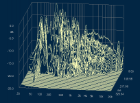
Very little of your cumulative spectral decay (CSD) plot is useful because very little of it shows the behavior of the device under test (DUT). Most of your plot shows the behavior of the nearby boundaries in your measurement setup. When you are interested in characterizing the DUT, you need to place your DUT and microphone as far from reflective boundaries as possible.
These are a couple of simple illustrations of the problem:


This is someone’s extravagant effort to avoid measurement reflections:

These are a couple of Pat Brown’s excellent diagrams showing how to deal with the problem far more easily:


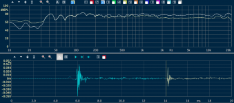
This is your measurement’s time domain using the energy time curve (ETC) to show the reflections:

In order to look at the DUT alone and exclude the reflections from your measurement, you can place the Auto Half-Hann window just before the first reflection as shown in the following plot. Because the 1st reflection in your measurement is so close to the DUT’s arrival, you are limited to a frequency resolution from about 850Hz up. This means that the trace under 850Hz is not accurate.

There is no smoothing in any of these measurements because it isn’t needed when you use windowing correctly. Smoothing should be avoided when possible because it reduces accuracy.
With the windowing set properly, we now have a CSD plot that characterizes the DUT without the environmental reflections:

This is the Wavelet Cycle view of the same measurement with the same windowing:

Last edited:
Crossover Simulation software using CLIO data
What would be the most suitable simulation software that imports the CLIO data and one can design/simulate the crossover components seeing the effects on the curves?
(And...if it also runs on a macbook it would be even better for me ;-) )
What would be the most suitable simulation software that imports the CLIO data and one can design/simulate the crossover components seeing the effects on the curves?
(And...if it also runs on a macbook it would be even better for me ;-) )
The Clio Export is a simple CSV format, that can be imported by all Speaker Simulation programs, like Vituixcad, LSPCad, ...
I don't know which are running on MacOS ?
Sorry for the delay answering. In the meantime I use Xsim with excellent results in combination with wine/winebotler on my Mac.
Reflections
So, I use the feature to take out the reflections and I get the de-reflected (?) curve. Now, I would like to have others to chime in for their interpretation.
Am I correct in understanding that the cleaned up curve is to get the most realistic speaker curve (without room) but that the reflective curve is the most realistic for listening and even to further tweak position and Xover of the speaker since after all we're listening to this speaker+room+diffraction curve?
Attachments
Hi Arno:
There still are a lot of later arrivals in your plot. It is absolutely the goal to measure the loudspeaker’s behavior alone without the room when wanting to improve the loudspeaker. Once again it would be helpful to post the measurement file in zip format so we can have a look at it.
At the end of your post you asked a question that if honestly addressed will put you on a life-long odyssey. I hope the following will be helpful to those that want to go further.
Some thoughts
1. As indicated in my last post, there is a very good reason that people expend great effort and expense to make anechoic loudspeaker measurements. Anechoic means without echoes, thus the first goal is to characterize loudspeaker behavior alone.
2. EQ, crossover adjustments, inverse filters (FIR), etc., can only change the output of the loudspeaker. These adjustments cannot perform magic, such as making walls disappear. This is the origin of the unpopular, but correct statement that "you cannot EQ a room".
3. Assume you have a perfect pair of loudspeakers. As soon as you place them in a room, the reflections add to the perfect first arrivals and distort the sound delivered at a given location. Move your head a couple of centimeters and the direct/reflected soup changes. You can apply a reciprocal distortion to the program content being sent to the loudspeakers through inverse filtering, but that will only improve one listening position at the expense of every other position. Even this one "sweet spot" will be compromised compared to addressing the root of the problem.
4. One way to address the issue is to throw away your loudspeakers and use headphones, but correctly designed loudspeakers in correctly designed rooms deliver superior music reproduction.
5. The requirement is to address causes instead of symptoms. The science of loudspeaker design is quite involved as is the science of room acoustics. Both pursuits submit to the science of hearing and perception. Regardless of money and effort spent, most will never experience the revelation of a home reproduction system that addresses each of these realms properly.
The beginning of the journey
1. Protect your hearing.
2. Attend serious music (non-amplified) events regularly.
3. Take each of these online courses.
4. Watch this.
5. Read this book once a year for the rest of your life.
Just triggering to see where others are in this.Can't zip the file since it's gone and I proceeded the fine tuning.
"life-long odyssey" , indeed it is, been designing/measuring/simulating and building loudspeakers for 35 Years now and I am still eager to take it the next step further.
Measurements are the combination of close up, in-room (even average up to 1/3 oct), 2m, listening position and...cutting out the reflections in CLIO.
Above all, listen to music a lot.
So, for me it's actually not a journey that begins
, got the Toole book and youtube and many others....great passion!The thing is, that I would like to see others diving deeper into this to share their findings, strategies etc...
Installing Clio pocket drivers
I have Clio Pocket installed in an old Win XP computer ( 32 bit ) with no problem. However I can't install the drivers in another computer with Win7 Ultimate ( 64 bit) and another with Win 7 Pro (64 bit).
I tried to disable Secure Boot as instructed by Audiomatica but it does not work. The drivers won't load. Maybe I'm doing something wrong. However I was able to load it successfully on a laptop with Win7 Home Basic PC ( 32 bit ) from 2011.
Is this because the problem machines are 64 bit ? Secure Boot apparently came in with Win8 ? I feel maybe the drivers work properly in a 32 bit system. Would anyone know how to get around this problem. Thanks for any help you can give.
Hello Ashok:
64bit is actually better. Also, only fairly new computers with Windows 10 tend to have the secure boot "feature", but you are wise to look because if it does exist, it needs to be disabled in BIOS.
CLIO Pocket comes with (2) USB drivers, one for XP and the other for the newer OS's.
Here's a link to the newer drivers.
- Home
- Design & Build
- Equipment & Tools
- CLIO Pocket