The times I look at old Tektronix schematics and you have to admire the amazing creativity!
You are a kindred spirit to the late Jim Williams.
You are a kindred spirit to the late Jim Williams.
And we share the same initials
")
RNMarsh,
If you get a chance try and pick-up the later 7904A - its basically the 7104 but without the MCP tube - its a much more modern mainframe the then non A version. The only thing I miss on the 7904A is the current probe calibrator - the little plastic "Handle" on the 7904 front panel.
Thank you for the very kind offer of the S6, but I've moved on from the 7S12 / 7S11 & 7T11 combinations, I've bought some rather nice Agilent 86100C's mainframes with the 20GHz & 50GHz plug-ins... Also, I'm not so involved in ultra fast pulse work these days... I do miss the cutting edge - but Audio's OK, but lacks that small community of really cutting edge research.
It saddens me that there are so few "true" designers in Audio - thinking back to the days of Quad current dumping etc. Today you see someone just rediscover some prior topology that no one would have battered an eyelid for, and now its like they are Semi Gods in the world of HiFi...
The times I look at old Tektronix schematics and you have to admire the amazing creativity! Yet, in HiFi people still flog old Class A/B designs with all the Phase / Gain modulation that occurs around the zero crossing point - such is our "Art"...
I just get a little disillusioned as there is so little genuine creativity to stimulate the mind and go - Erh, that's clever!
Hi,
The 7904 does have the current probe calibrator loop on the front panel. I bought another (might have been a A-version.. thrown away now) for parts... I swapped out the character generator pcb to get that working again. Kept a lot of other parts for spares. I also keep a lot of TEK educational series binders when I can find them.
I can Only go to 6Ghz with a nice HP Network analyzer with color display..... it also just needed trouble-shooting and minor repair and it is working fine. Saved a lot of money if you can fix some of this, otherwise, expensive gear.
yes, life is pretty tame after you've worked your way up to cutting edge stuff but I now have a pretty good collection of test equipment for just about any hobby in electronics. At fist, I was bored being retired.... but as time went by, i now do not have enough hours in the day and stay up to at least midnight every night on my projects. Learning and exploring is still fun for me.
THx-RNMarsh
Last edited:
for basic functionality debugging there is little need for super low distortion sine - eyeballs on 'scope traces are hard pressed to see a few %
the traditional sine/square/triangle function generator is very handy for the eyeball and scope phase
I am amazed that advanced diyers care about Class B errors - I thought everyone agrees that ~100 mA per output Q is a good place to AB
Cordell's HEC Mosfet power amp article is over 30 years old
we have Geometric mean, Pass nonswitching output, Hegglun's square/cube bias
Quad style feedforward seems of limited use in audio power amps to me:
and the PIM speculation has been theoretically straightened out for 30 years if you read Cordell, Cherry; Jung and Leach "switched camps" after some toying with Otala's ideas - concluded his prescription was wrong
we're still waiting for the psychoacoustic evidence that "PIM"/"FM" IMD is any more audible/objectionable then "AM" IMD - both are measured by conventional IMD test - just not separated like Cordell's custom quadrature IMD measurement hardware did
the traditional sine/square/triangle function generator is very handy for the eyeball and scope phase
I am amazed that advanced diyers care about Class B errors - I thought everyone agrees that ~100 mA per output Q is a good place to AB
Cordell's HEC Mosfet power amp article is over 30 years old
we have Geometric mean, Pass nonswitching output, Hegglun's square/cube bias
Quad style feedforward seems of limited use in audio power amps to me:
I've read up on Black's Feedforward, Quad, Vanderkooy (…and Annison, Danyuk, Sandman, Stochino) paper's circuits, simmed a few alternatives
after thinking about it I come to the question that if you can measure the error to amplify and add in to cancel the main amp distortion - why don't you just use more feedback?
for audio power amps we have the ability to use plenty negative feedback loop gain over an extended definition of audio frequency range if allowed to use RET or MOSFET output Q to push unity loop gain intercept up and use higher order compensation, or nested feedback (including Bob's, Hawksford's EC)
feedback error disappears into noise for really high loop gain feedback amps except for the last few octaves of audio
the feedforward schemes can knock down the >20 kHz errors ~ 20-30 dB – but at some cost in parts, design complexity for arguably inaudible “improvement”
and the cancellation is very sensitive to gain/power coupling network tolerances
remember also that the audible IMD products are reduced by the feedback at the product frequency – so any high frequency difference products folding down into audio are reduced by the high loop gain feedback
feedforward may just reduce Bob's THD 20 kHz metric without adding to/giving any of the implied "goodness" at actually audible frequencies that we hope the THD20 correlates with
http://www.diyaudio.com/forums/solid-state/184725-alternative-topologies-3.html#post2506046
http://www.diyaudio.com/forums/soli...in-composite-op-amp-circuits.html#post2415805
and the PIM speculation has been theoretically straightened out for 30 years if you read Cordell, Cherry; Jung and Leach "switched camps" after some toying with Otala's ideas - concluded his prescription was wrong
we're still waiting for the psychoacoustic evidence that "PIM"/"FM" IMD is any more audible/objectionable then "AM" IMD - both are measured by conventional IMD test - just not separated like Cordell's custom quadrature IMD measurement hardware did
Quad style feedforward seems of limited use in audio power amps to me
Well each person to there own, but I find increasing THD with Increasing frequency as the loop-gain is reduces is an undesirable characteristic!
Due to the reactive component in the Bridge, Quads current dumping works as a standard feedback amplifier at lower frequency and then at some point where the negative feedback would normally be ineffective the bridge circuit takes over - on the bench I easily get over 40dB improvement (normally over 50dB improvement), which is not to be sniffed at. I've amplifier designs that have THD results of -140dB at 20KHz - I've not seen a standard ClassAB come near.... although I could have been looking in the wrong places?
The other advantage (with Quads clever circuit arrangement as a result of introducing a voltage offset between the ClassA stage and the ClassC dumpers) is that the ClassA stage is always in control of the load - this results in a significant improvement in PIM results, THD & sound quality.
I have no idea about Otala's ideas it this was all before my time - but PIM very much shows up as a dynamic non linear Jitter of the amplifiers output - I find that when efforts are made to reduce this "Time domain variation" then the sound stage abilities of the amplifier are improved - and too my ears atleast the same sonic effect caused by jitter on Digital ADC / DAC conversion.
Class AB operation is especially horrible with Bipolar devices due to the abrupt change of impedance as the non operating device "snaps off" when operated in the opposite quadrant - non switching solutions resolve these problems and the "Sharp" impedance discontinuity is less of a problem with MOSFET (especially lateral type) devices which have a much softer and gradual handover - VFETs are so "soft" its hard to switch the buggers off completely!
IMO, I suspect that the softer and gradual handover of MOSFET is one of the reasons Mosfet amplifiers sound better then there transistor counterparts.
I don't wish to get into infinite-loop arguments at PIM, but I find that designs with very low PIM are able to portray a vast left to right sound stage with discrete instrument placement, where as designs with much poorer PIM results which are invariably ClassAB lack the ability to recreate a nice wide "expansive" sound stage, so its case closed for me.
Looking at the open loop dynamic Gain modulation of a class AB design with its violently abrupt discontinuities and variations is just so horrid that it has to impact the sound quality...
Each designer spins his designs his own way, dynamic OL Gain Modulation, increasing HF distortion and resultant PIM and Dynamic output impedance variations are a VERY BIG no no for me!
The great advantage of spice simulation is that one is able to analyse what would be otherwise very difficult circuit characteristics to measure in the "physical world".
I'm trying to correlate what I hear during listening tests with results from simulation & hardware measurements, and am discovering that the Time domain performance is extremely important - although I don't believe there is agreement why (the same with the time domain performance of digital filters etc).
In my own lab / studio tests PCM digital even at 192KHz cannot recreate the realism of 1inch Master tape (the difference is just shocking), although we all know tape has inferior technical measurements - yet a pure DSD recording of Master tape is atleast to my ears is all but indistinguishable to the tape master... and the simple fact is that DSD has superior time domain performance to PCM digital.
DSD increased Data BW is in the time domain, while HiRes PCM is in the amplitude domain.
Last edited:
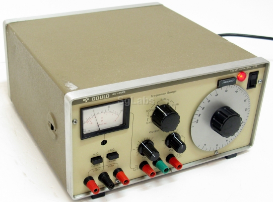
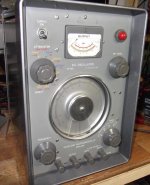
The local hackerspace received a "classic" equipment donation including several HP-200 to HP-202 models. Some people want to get rid of it all. We also have a small solid-state sine/square/triangle generator, but I like an old HP generator with the nice big dial and vernier knob for sweeping to get a woofer's free-air resonant frequency.for basic functionality debugging there is little need for super low distortion sine - eyeballs on 'scope traces are hard pressed to see a few %
the traditional sine/square/triangle function generator is very handy for the eyeball and scope phase
I'm also disappointed that some 'classic' analog function chips such as the 8038 are no longer made (the manufacturer's buzzword is "obsolete"). There were also the more specialized SSM and CEM analog music synthesizer chips that are now collectible. A well-programmed microcontroller can do at least as well, but it needs more than a cap and a few resistors to get going.
While I'm going there, why don't modern digital generators have a knob on a quadrature encoder to control frequency? Must be a little more expensive than pushbuttons. Last I saw one was on a logic analyzer.
can't you find a smart phone app with a touch slider for frequency?
I do understand liking classic equipment but there is also competition for bench space
has no meaning for audio bandwidth - I have posted 16/44 round trip through .wav that show sub-nanosecond time resolution of enveloped tones that would approximate musical notes
24/196 would blow right past SACD 2.8 Mb for audio frequency event time-frequency/phase accuracy - time and frequency/phase are mathematical Duals - more bits dedicated to the audio bandwidth, the greater S/N of hi rez PCM let you locate with greater accuracy than DSD
I do understand liking classic equipment but there is also competition for bench space
...and the simple fact is that DSD has superior time domain performance to PCM digital
has no meaning for audio bandwidth - I have posted 16/44 round trip through .wav that show sub-nanosecond time resolution of enveloped tones that would approximate musical notes
24/196 would blow right past SACD 2.8 Mb for audio frequency event time-frequency/phase accuracy - time and frequency/phase are mathematical Duals - more bits dedicated to the audio bandwidth, the greater S/N of hi rez PCM let you locate with greater accuracy than DSD
Last edited:
JCX,
While its true to say that PCM192 KHz has greater amplitude resolution at higher frequency, DSD has greater resolution at lower frequency where our ear is most sensitive so it could be rightly argued in my opinion that DSD's has superior amplitude resolution where its required the most.
I'd need to look back at some of my noise shaper simulation work, but the crossover where DSD start to loose out to PCM resolution was quite highup, IIRC something like 15KHz - so below 15KHz DSD has superior Amplitude resolution over 24Bit PCM.
At 1KHz DSD resolution is typically around 165dB depending upon the noise shaper order etc. where as PCM 24bits is -144dB.
DSD also has extended Frequency range into the MHz region with no Brickwall filter - and as any AudioLab MDAC owner can try for themselves, digital filter have a significant impact on the sound quality. For the MDAC we designed filters (optimal Transient filters) which preserve the time domain accuracy over amplitude accuracy and I believe just about every MDAC owner listens with one of the Optimal transient type filters.
WRT DSD timing accuracy, DSD is sampled at 2.8MHz so has 2.8 milion sample points per second, where as PCM has "only" 192,000 - with this in mind its hard to argue that PCM has greater time domain accuracy, its simply cannot as it does not have the original data captured.
We are not talking about capturing a continues test tone, but an instantaneous "transient event" - which is the real nature of music, for that more data points are always going to win.
While you could argue that PCM 192KHz has adequate time resolution within the audio B/W, but if that is so, then why is it that DSD is able to capture the the very fine transient details in music and sound "real & natural", while PCM 192KHz just sound like a cheap imitation?
About 8 years ago, I designed a digital delay-line that we could switch the ADC / DAC between PCM & DSD naive modes. This "switch" just configured the interfaces of the ADC / DAC between Native DSD path or PCM, so nothing changed in the circuit, only the mode of operation. The sampling rate was about 216KHz (PCM).
We had a 3 postion switch so we could not tell which mode was selected, just A, B, C (two modes where the same) - the difference was so great that to this day I've not forgotten the test. It was one of those landmark moments in a designers life.
The delay line was used to compensate the "time of flight" of a folded Bass horn and the MID / HF units, used in high power outside concert events - I was lucky enough to have spent alot of time working with live music - but even off Master tape the effect of DSD verses PCM was the same, maybe more so as you where in a lower pressure environment you did not need to worry about things going on around you.
Here is a picture of an early prototype of the Delay line PCB...
This was just an early spin of the design, I don't seem to have a record of the final version - once we had settled on DSD Mode I dropped the expensive TI DAC and just designed a simple 1 BIT DAC keeping the PCM4202 ADC for its Pure 1Bit output into the memory delay circuit.
I tried to design out the PCM4202 ADC but with a limited budget and PCB space it was not possible to insure no fixed idle tones with the simple 1 bit modulator design... the PCM4202 has very good idle tone suppression.
At the end of the day, your welcome to your beliefs, I've development mine though my own R&D and a lifetimes experience of building and listening to designs including silicon IC's
While its true to say that PCM192 KHz has greater amplitude resolution at higher frequency, DSD has greater resolution at lower frequency where our ear is most sensitive so it could be rightly argued in my opinion that DSD's has superior amplitude resolution where its required the most.
I'd need to look back at some of my noise shaper simulation work, but the crossover where DSD start to loose out to PCM resolution was quite highup, IIRC something like 15KHz - so below 15KHz DSD has superior Amplitude resolution over 24Bit PCM.
At 1KHz DSD resolution is typically around 165dB depending upon the noise shaper order etc. where as PCM 24bits is -144dB.
DSD also has extended Frequency range into the MHz region with no Brickwall filter - and as any AudioLab MDAC owner can try for themselves, digital filter have a significant impact on the sound quality. For the MDAC we designed filters (optimal Transient filters) which preserve the time domain accuracy over amplitude accuracy and I believe just about every MDAC owner listens with one of the Optimal transient type filters.
WRT DSD timing accuracy, DSD is sampled at 2.8MHz so has 2.8 milion sample points per second, where as PCM has "only" 192,000 - with this in mind its hard to argue that PCM has greater time domain accuracy, its simply cannot as it does not have the original data captured.
We are not talking about capturing a continues test tone, but an instantaneous "transient event" - which is the real nature of music, for that more data points are always going to win.
While you could argue that PCM 192KHz has adequate time resolution within the audio B/W, but if that is so, then why is it that DSD is able to capture the the very fine transient details in music and sound "real & natural", while PCM 192KHz just sound like a cheap imitation?
About 8 years ago, I designed a digital delay-line that we could switch the ADC / DAC between PCM & DSD naive modes. This "switch" just configured the interfaces of the ADC / DAC between Native DSD path or PCM, so nothing changed in the circuit, only the mode of operation. The sampling rate was about 216KHz (PCM).
We had a 3 postion switch so we could not tell which mode was selected, just A, B, C (two modes where the same) - the difference was so great that to this day I've not forgotten the test. It was one of those landmark moments in a designers life.
The delay line was used to compensate the "time of flight" of a folded Bass horn and the MID / HF units, used in high power outside concert events - I was lucky enough to have spent alot of time working with live music - but even off Master tape the effect of DSD verses PCM was the same, maybe more so as you where in a lower pressure environment you did not need to worry about things going on around you.
Here is a picture of an early prototype of the Delay line PCB...
An externally hosted image should be here but it was not working when we last tested it.
This was just an early spin of the design, I don't seem to have a record of the final version - once we had settled on DSD Mode I dropped the expensive TI DAC and just designed a simple 1 BIT DAC keeping the PCM4202 ADC for its Pure 1Bit output into the memory delay circuit.
I tried to design out the PCM4202 ADC but with a limited budget and PCB space it was not possible to insure no fixed idle tones with the simple 1 bit modulator design... the PCM4202 has very good idle tone suppression.
At the end of the day, your welcome to your beliefs, I've development mine though my own R&D and a lifetimes experience of building and listening to designs including silicon IC's
Last edited:
Another one:
Krohn-Hite 4402B Ultra-Pure Sinewave Oscillator 1Hz to 110kHz | eBay
I would start at an $200,-- offer.
Good for THD -120dBc and better after some opamp rolling.
Did it, worked out, R.N. Marsh modded his too, with good results.
The unit finally arrived here in the not so sunny Czech Rep.
I'll perform some measurements on it once the Wife returns so she can mind the pups and I can get to my lab... The pups are not very happy in the lab yet they need to settle and find there place.
I wonder how it performs in unmodified form.
The front panel has badly yellowed, with lighter patchy areas which where hidden from UV by Calibration labels etc.
I picked up a second hand one off ebay.
Had it for around 8 years now and it still works fine.
Which unit?
OK, fist problem I've encountered with the 4402B is that the Latching / unlatch bar that runs between the Freq Multiplier buttons is sticky and the end spring cannot return it to the null position so the buttons will not stay depressed once selected - when my Wife returns with the car I'll pop out and purchase some WD40...
Based upon component date codes the unit appears to have been built sometime from 1999 onwards.
PCB's very clean inside - not much to the design.
Based upon component date codes the unit appears to have been built sometime from 1999 onwards.
PCB's very clean inside - not much to the design.
Good old WD40 carefully sprayed with its "Smart Straw" free'd the sticky Latch bar, looks like the grease had become too sticky over the years and gummed up the latch bar.
Buttons now have a solid firm click as they are selected.
Off to the to the lab later for performance measurement - I hope the unit has a lower noise floor then my UPD's own internal analogue generator, whose Gens' FFT noise floor is about -150dB down Ref. 1V RMS....
Buttons now have a solid firm click as they are selected.
Off to the to the lab later for performance measurement - I hope the unit has a lower noise floor then my UPD's own internal analogue generator, whose Gens' FFT noise floor is about -150dB down Ref. 1V RMS....
So the Krohn Hite 4402B 1KHz, 2Vrms Single ended output.
THD -123dB which is about 2dB worst then my UPD Sig Gen.
The FFT noise floor (16K points) is about -150dB or so, the above FFT was measured with at a 6Vrms analysers input gain setting so the noise is higher, but squeezes a slightly lower THD from the UPD's ADC's.
No second harmonic - only third onwards which could typically be a result of the Voltage coefficient of resistors etc.
There is also quite a bit of Mains related noise below 1KHz.
THD -123dB which is about 2dB worst then my UPD Sig Gen.
An externally hosted image should be here but it was not working when we last tested it.
The FFT noise floor (16K points) is about -150dB or so, the above FFT was measured with at a 6Vrms analysers input gain setting so the noise is higher, but squeezes a slightly lower THD from the UPD's ADC's.
No second harmonic - only third onwards which could typically be a result of the Voltage coefficient of resistors etc.
There is also quite a bit of Mains related noise below 1KHz.
Last edited:
JCX,
While its true to say that PCM192 KHz has greater amplitude resolution at higher frequency, DSD has greater resolution at lower frequency where our ear is most sensitive so it could be rightly argued in my opinion that DSD's has superior amplitude resolution where its required the most.
Do you know of any reliable evidence that PCM192 inherently adds audible artifacts to music? If there is no such thing, and I know of no such thing, then the discussion of PCM192 versus DSD SQ would appear to be moot.
I a lucky to have a Tektronix SG5010 programmable low distortion oscillator, with the accompanying AA5001 distortion analyser. Even with this I now want a 24bit/384Khz DAC/ADC so I can do FFT. Outboard USB boxes exist to do this.
I was fortunate to pick up a set of these after the Dot-Com bubble burst. They are a bit pricey.
Dead link
John,
any chance you still have the 4402B service manual? The dropbox link you provided (in 2015) is now dead. Sadly, so is my 4402B.
Thanks!
-Vin
Kindly forward by ghg:-
Krohn Hite 4400A Service manual:-
Dropbox - 404
Krohn Hite 4402B Service manual:-
Dropbox - 404
John,
any chance you still have the 4402B service manual? The dropbox link you provided (in 2015) is now dead. Sadly, so is my 4402B.
Thanks!
-Vin
- Status
- This old topic is closed. If you want to reopen this topic, contact a moderator using the "Report Post" button.
- Home
- Design & Build
- Equipment & Tools
- The disappearance of analog audio signal generators