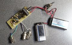
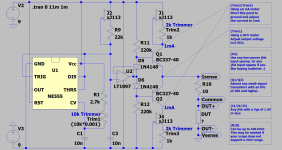
This is an small/simple tool to do in-circuit curve tracing. The tool injects voltages up to +/- 5V and currents up to +/- 1V into the DUT (or circuit under test) and draws a curve on a x-y scope (any scope with an x-y setting). The injected voltages and current should be safe with most/any circuit.
The tester can be used to compare two circuits (one working and one that lost some of it's smoke), differences between the two circuits are visible through different traces that are displayed. This I.G.C. tester can very quickly pinpoint components or circuit parts where faults may be located. No need to de-solder any component")
The tester can be used to compare two circuits (one working and one that lost some of it's smoke), differences between the two circuits are visible through different traces that are displayed. This I.G.C. tester can very quickly pinpoint components or circuit parts where faults may be located. No need to de-solder any component
Attachments
Last edited:
This method is not unknown in the industry:
http://www.polarinstruments.com/pdf/brochures/PFL.pdf
The disadvantage is that it can't be accurate in case of extremely low or high impedances and a functioning reference circuit is needed for the comparative measurement.
http://www.polarinstruments.com/pdf/brochures/PFL.pdf
The disadvantage is that it can't be accurate in case of extremely low or high impedances and a functioning reference circuit is needed for the comparative measurement.
This method is not unknown in the industry:
http://www.polarinstruments.com/pdf/brochures/PFL.pdf
The disadvantage is that it can't be accurate in case of extremely low or high impedances and a functioning reference circuit is needed for the comparative measurement.
But it is simple, cheap and can be build from the bin. One more tool to use, and can be very useful.
My imagination is also limited regarding the amount of applications which this DC OFFSET injector can show some usability.
Other than testing the X-Y functionality of old analogue Oscilloscopes, just for a simple visual verification of their internal circuits.
The injector is not an precision device, and therefore it can not be used as measuring standard, regarding fine adjustments.
Possibly this design is trying to mimic partial of the functionality of the components tester which was an option in some old Oscilloscopes at 80s.
My imagination is also limited regarding the amount of applications which this DC OFFSET injector can show some usability.
Other than testing the X-Y functionality of old analogue Oscilloscopes, just for a simple visual verification of their internal circuits.
The injector is not an precision device, and therefore it can not be used as measuring standard, regarding fine adjustments.
Possibly this design is trying to mimic partial of the functionality of the components tester which was an option in some old Oscilloscopes at 80s.
I fail to see why the negative approach, the tester can be used for quick fail/pass testing of capacitors, transistors, diodes and alike. The measurements are just a quick indication on where to start, but some times that is all you need. If you like it, build it, of not then don't. But for 0$'s of parts from the bin, it can not be a bad investment.
The unit shown was designed, build and used yesterday evening, in one specific job where it did some good, and I thought to publish it just because it was there
And I have no idea what kind of component tester was part of these old scope (in those day's (the 70s and 80s) I mainly used Tek's and they did not feature such testers.
Last edited:
Neither do I: although I am no great fan of these instruments, I do have a salvaged one (a "Vu-Data", a copy of the polar) that sits on my bench and is always on (via the master switch).I fail to see why the negative approach,
It is useful where an ohmmeter or a diode test becomes insufficient: suppose you suspect a shorted turn or winding on a transformer: with just an ohmmeter, the difference between bad and good will be negligible, but with such a tester, you will see either a diagonal line or an open figure, depending on the condition of the transformer.
It is just one example, and there are many others. As I said, I am no great fan, but nowadays I do little repair and maintenance jobs, and I have more specific instruments at my disposal, but for someone doing repair jobs on SMPS's and similar all day long, such a help is certainly welcome, as it spares tedious desoldering time.
You have to become accustomed to it, know how to interpret the figures, but once you do, if you know your theory, it can be useful and time-saving.
It is a matter of taste too, but I see no reason to be that negative towards a carefully thought-out and potentially very useful contribution.
If you don't like it, why not develop and present your own ground-breaking tester?
Otherwise, just live and let live...
Here is an illustration of the example I gave: the first pic displays the normal behavior of a mains transformer's primary and the second is the same, but with a winding shorted. Pretty obvious, even to the untrained eyes, but a simple ohmmeter test doesn't provide even the beginning of a clue.
Lesson to be learned: do not dismiss too lightly what you are unfamiliar with, or don't understand....
Lesson to be learned: do not dismiss too lightly what you are unfamiliar with, or don't understand....
Attachments
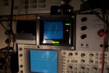
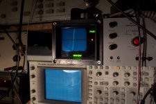
Here is an illustration of the example I gave: the first pic displays the normal behavior of a mains transformer's primary and the second is the same, but with a winding shorted. Pretty obvious, even to the untrained eyes, but a simple ohmmeter test doesn't provide even the beginning of a clue.
Lesson to be learned: do not dismiss too lightly what you are unfamiliar with, or don't understand....
Thanks Elvee, useful information.
I fail to see why the negative approach
Is it your hobby to analyze other people emotions?
In an anonymous forum there is no possitive or negative approach, but readers who has their own opinion.
Is it your hobby to analyze other people emotions?
In an anonymous forum there is no possitive or negative approach, but readers who has their own opinion.
Language is a funny thing, I did say 'negative approach', I did not say that you where negative in any way or form. You where negative about the capabilities and application of the tool, and I can (still) not see why this was needed. No need to analyze any one's emotions, just read what is there.
- Status
- This old topic is closed. If you want to reopen this topic, contact a moderator using the "Report Post" button.
- Home
- Design & Build
- Equipment & Tools
- In-Circuit General-Purpose Curve-Tracer