RIT does not have a senior design requirement for my program. They do have 3 credit Independent Study options. Graduation technically was in May, but I opted to stay the summer for an Independent study. I am referring to this as my senior project. The professor and I agreed that it would be OK if I complete part of the unit over the summer and the rest after I graduate. Therefore, I still am developing the unit.
This unit is a computerized curve tracer for vacuum tubes. There are several designs and successful DIY units. I found they all have serious limitations of some kind. Plus, I believe in originality and do not like to directly copy existing designs (the Chinese and Russians may feel otherwise here ). I do like to base my designs on others at times. If there was not a healthy balance between originality and some recycling of existing ideas, there would not be evolution and innovation. Engineering ethics was one of my favorite classes.
Overview:
Basically, the unit needs to be able to trace fully small signal tubes up to large power tubes such as the KT150.
There is no guarantee a tube will not have a fault. The curve tracer must be able to identify and protect against faulty tubes and careless use. Furthermore, safety is a requirement. It will not operate unless a cover is in place that protects the user.
A VB app is in charge of drawing the curves on the computer screen and providing an interface for the user to set up tests. The app also formats the curves, allows for printing, etc. The best feature the VB app will have is a juxtaposition feature. This allows users to compare curves between two or more tubes for matching, etc.
Physical Design:
A steel enclosure from an old Heathkit distortion analyzer was selected for the electronics enclosure. An aluminum patch panel with 7 pin, 9 pin, and 8 pin sockets will make up the top of the unit. Banana connectors are used to wire the various socket pins to the various systems of the curve tracer. Ferrite beads may need to be installed in the cables to stop potential oscillations in high gain tubes.
A cover closes over top of the panel and DUT to protect the user, triggering a switch mounted under the chassis. The electronics are mounted on 5 individual 6x15 cm circuit boards. These modules are categorized into separate systems, each responsible for a unique function in the unit.
The Five Systems:
- Main Controller.
The main controller is responsible for monitoring and controlling all other systems in the unit. It also monitors the voltage and current sensors for the device under test. Once data is collected from these sensors, it is uploaded via UART to the PC. The VB app then deals with deducing curve information from the raw samples through DSP techniques. A Cypress Semiconductor Programmable System On A Chip (PSoC 5) performs the bulk of functionality on this board. This chip by nature allows for flexible designs and is extremely powerful.
PSoC 5LP - Cypress
To keep high voltage away from the sensitive logic circuity, and PCs connected, A7800A isolating amplifiers are utilized. These ICs are designed for industrial polyphase motor control. Large bolt on connectors accommodate connectivity from the current shunt and voltage sensors.
- B+ Sweep.
A large complicated linear regulator is not necessary here. Rectified B+ pulses are simply applied directly to the plate. This technique is based off the Tektronix 576 1950s era curve tracer. The mains voltage is fed via a multitap transformer into SCR's. Each tap represents a peak voltage range. The main controller through optocouplers can switch the various ranges to the plate. A non-invasive current shunt and resistive divider form a current and voltage detector for the DUT.
- Step amplifiers.
This board is responsible for supplying grid bias and screen grid power. The grid bias uses an op amp, controlled by an isolated DAC. This supply can sweep from 0 to -100 volts. The screen grid uses a PAD195 (these were expensive, but RIT paid for them) discrete power op-amp module, controlled by the same DAC. This supply ranges from 100 to 400 volts (I may tweak it later) and is current limited to 22mA.
PAD195 Datasheet for Power Op Amps, High Voltage Op Amps, High Current Op Amps
Dennis Eddlemon, the gentleman that runs that outfit is a very nice, helpful individual. He also designed the APEX units when he worked there.
- Circuit protection board.
A series of shunt monitors, instrumentation amplifiers, and comparators are the crux of this circuit. If any one of the elements is found to be drawing too much current, the comparator will assert an interrupt singling the main controller to remove power to all the elements using solid state relays. The controller will then signal the PC where the fault lies.
Since the SCR tap selection technique provides only coarse control, a software programmable overvoltage and power protector removes power when a 120 cycle hump exceeds the programmed ratings. This protects tubes from being stressed or ruined by the tester. The VB application allows users to dial in maximum plate dissipation and maximum plate voltages.
-Heater Regulators
- This module utilizes DAC controlled TI simple switcher units. These power supplies deliver 0.8-30 volts over two ranges to power the heaters of the tubes. Switchers are used for efficiency. Imagine powering a 2A3 from a linear regulator with 6.3 volts in. A lot of watts to get rid of! A standard power transformer feeds the switchers through a full wave bridge.
Here is an overall of how the unit will work:
1. A user places a tube in the tester, wires the patch panel, and closes the cover.
2. He/She through the Visual Basic application specifies the following parameters:
4. The heater supply kicks on.
5. The tester waits for the duration of the heater warmup time parameter.
6. The ADC begin sampling the shunts at zero crossing.
7. If the overvoltage or power guard is tripped:
9. Steps 6 to 8 repeat until the lowest grid bias value is reached.
10. Visual basic runs the DSP and other algorithms to plot the curves.
This unit is a computerized curve tracer for vacuum tubes. There are several designs and successful DIY units. I found they all have serious limitations of some kind. Plus, I believe in originality and do not like to directly copy existing designs (the Chinese and Russians may feel otherwise here
). I do like to base my designs on others at times. If there was not a healthy balance between originality and some recycling of existing ideas, there would not be evolution and innovation. Engineering ethics was one of my favorite classes.Overview:
Basically, the unit needs to be able to trace fully small signal tubes up to large power tubes such as the KT150.
There is no guarantee a tube will not have a fault. The curve tracer must be able to identify and protect against faulty tubes and careless use. Furthermore, safety is a requirement. It will not operate unless a cover is in place that protects the user.
A VB app is in charge of drawing the curves on the computer screen and providing an interface for the user to set up tests. The app also formats the curves, allows for printing, etc. The best feature the VB app will have is a juxtaposition feature. This allows users to compare curves between two or more tubes for matching, etc.
Physical Design:
A steel enclosure from an old Heathkit distortion analyzer was selected for the electronics enclosure. An aluminum patch panel with 7 pin, 9 pin, and 8 pin sockets will make up the top of the unit. Banana connectors are used to wire the various socket pins to the various systems of the curve tracer. Ferrite beads may need to be installed in the cables to stop potential oscillations in high gain tubes.
A cover closes over top of the panel and DUT to protect the user, triggering a switch mounted under the chassis. The electronics are mounted on 5 individual 6x15 cm circuit boards. These modules are categorized into separate systems, each responsible for a unique function in the unit.
The Five Systems:
- Main Controller.
The main controller is responsible for monitoring and controlling all other systems in the unit. It also monitors the voltage and current sensors for the device under test. Once data is collected from these sensors, it is uploaded via UART to the PC. The VB app then deals with deducing curve information from the raw samples through DSP techniques. A Cypress Semiconductor Programmable System On A Chip (PSoC 5) performs the bulk of functionality on this board. This chip by nature allows for flexible designs and is extremely powerful.
PSoC 5LP - Cypress
To keep high voltage away from the sensitive logic circuity, and PCs connected, A7800A isolating amplifiers are utilized. These ICs are designed for industrial polyphase motor control. Large bolt on connectors accommodate connectivity from the current shunt and voltage sensors.
- B+ Sweep.
A large complicated linear regulator is not necessary here. Rectified B+ pulses are simply applied directly to the plate. This technique is based off the Tektronix 576 1950s era curve tracer. The mains voltage is fed via a multitap transformer into SCR's. Each tap represents a peak voltage range. The main controller through optocouplers can switch the various ranges to the plate. A non-invasive current shunt and resistive divider form a current and voltage detector for the DUT.
- Step amplifiers.
This board is responsible for supplying grid bias and screen grid power. The grid bias uses an op amp, controlled by an isolated DAC. This supply can sweep from 0 to -100 volts. The screen grid uses a PAD195 (these were expensive, but RIT paid for them) discrete power op-amp module, controlled by the same DAC. This supply ranges from 100 to 400 volts (I may tweak it later) and is current limited to 22mA.
PAD195 Datasheet for Power Op Amps, High Voltage Op Amps, High Current Op Amps
Dennis Eddlemon, the gentleman that runs that outfit is a very nice, helpful individual. He also designed the APEX units when he worked there.
- Circuit protection board.
A series of shunt monitors, instrumentation amplifiers, and comparators are the crux of this circuit. If any one of the elements is found to be drawing too much current, the comparator will assert an interrupt singling the main controller to remove power to all the elements using solid state relays. The controller will then signal the PC where the fault lies.
Since the SCR tap selection technique provides only coarse control, a software programmable overvoltage and power protector removes power when a 120 cycle hump exceeds the programmed ratings. This protects tubes from being stressed or ruined by the tester. The VB application allows users to dial in maximum plate dissipation and maximum plate voltages.
-Heater Regulators
- This module utilizes DAC controlled TI simple switcher units. These power supplies deliver 0.8-30 volts over two ranges to power the heaters of the tubes. Switchers are used for efficiency. Imagine powering a 2A3 from a linear regulator with 6.3 volts in. A lot of watts to get rid of! A standard power transformer feeds the switchers through a full wave bridge.
Here is an overall of how the unit will work:
1. A user places a tube in the tester, wires the patch panel, and closes the cover.
2. He/She through the Visual Basic application specifies the following parameters:
- Maximum plate dissipation and B+ voltage or less.
- Heater warmup time and voltage.
- Grid bias step value.
- Grid bias minimum value (negative numbers here).
- Screen voltage (pentode/tetrode assumed).
4. The heater supply kicks on.
5. The tester waits for the duration of the heater warmup time parameter.
6. The ADC begin sampling the shunts at zero crossing.
7. If the overvoltage or power guard is tripped:
- Power is removed from all elements except the heater.
9. Steps 6 to 8 repeat until the lowest grid bias value is reached.
10. Visual basic runs the DSP and other algorithms to plot the curves.
Very ambitious- and potentially very useful.
Had you considered using a heterodyning method as opposed to the usual step methods? If you chose, for example, 1000Hz for a grid signal and 1020Hz for a plate signal, you get a fresh set of curves 20 times a second. That could be useful for doing fun things like microphonics, or the influence of magnetic fields by moving a magnet in and out, or whatever. It would probably score you a few extra points with the prof as well.
Had you considered using a heterodyning method as opposed to the usual step methods? If you chose, for example, 1000Hz for a grid signal and 1020Hz for a plate signal, you get a fresh set of curves 20 times a second. That could be useful for doing fun things like microphonics, or the influence of magnetic fields by moving a magnet in and out, or whatever. It would probably score you a few extra points with the prof as well.
I like this idea !Very ambitious- and potentially very useful.
Had you considered using a heterodyning method as opposed to the usual step methods? If you chose, for example, 1000Hz for a grid signal and 1020Hz for a plate signal, you get a fresh set of curves 20 times a second.
You may even use random "noise" as long as you sample voltage(s) and current(s) simulaneously

Yves.
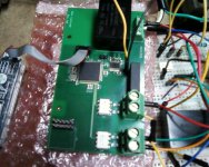
Over the summer, I successfully designed and debugged the Main Controller. A picture of it is attached. It is a 4 layer board I populated myself in RIT's surface mount lab.
The large 100 pin IC is the PSoC 5 controller. The smaller one is a MAX232 UART/TTL lever converter. The two white ICs are the 7840 isolating amplifiers.
Data Sheet - HCPL-7840, Isolation Amplifier (146 KB)
One measures the current shunt and the other the voltage shunt mounted on the B+ Sweep board. These ICs provide complete isolation. None of the measuring circuitry directly touches any ground as the lines are fully balanced.
The board has two signal layers (top and bottom), a ground plane, and a power plane. The large black power brick takes the mains down to an isolated 5 volts. The smaller brick takes the 5 volts and turns it into two seperate isolated 5 volt power supplies. Therefore I have 3 independent 5 volt supplies. One powers the high voltage half of the 7840s. The second powers the low voltage side, or the supply for the analog components. The third powers all the digital components. The ground plane is split into analog and digital parts and is joined back at the small power brick. Also, there is an isolated portion of it for the high voltage side of the 7840s. The same is true for the power plane. The tube B+, screen, and bias supplies have their own common High Voltage ground point. A ribbon cable connects to the header, providing digital power and a SPI interface to the rest of the boards.
I just finished testing the shunt measuring system today on the breadboard using a low voltage transformer and various resistors. Initially, I had some serious data corruption issues due to the lack of a common reference because of the isolation. What probably was going on was the measurements were being referenced to one another. Adding a cascade 7840 to the voltage shunt isolated the current measurement from the voltage. This double isolation now allows independent readings to be taken, yielding correct results.
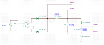
The schematic shows a very basic arrangement of the full system. Note the diodes are really the SCR's. The voltage shunt resistors are scaled so 600 volts peak results in the maximum 200mV into the amplifier. The same applies for the current shunt.
The large 100 pin IC is the PSoC 5 controller. The smaller one is a MAX232 UART/TTL lever converter. The two white ICs are the 7840 isolating amplifiers.
Data Sheet - HCPL-7840, Isolation Amplifier (146 KB)
One measures the current shunt and the other the voltage shunt mounted on the B+ Sweep board. These ICs provide complete isolation. None of the measuring circuitry directly touches any ground as the lines are fully balanced.
The board has two signal layers (top and bottom), a ground plane, and a power plane. The large black power brick takes the mains down to an isolated 5 volts. The smaller brick takes the 5 volts and turns it into two seperate isolated 5 volt power supplies. Therefore I have 3 independent 5 volt supplies. One powers the high voltage half of the 7840s. The second powers the low voltage side, or the supply for the analog components. The third powers all the digital components. The ground plane is split into analog and digital parts and is joined back at the small power brick. Also, there is an isolated portion of it for the high voltage side of the 7840s. The same is true for the power plane. The tube B+, screen, and bias supplies have their own common High Voltage ground point. A ribbon cable connects to the header, providing digital power and a SPI interface to the rest of the boards.
I just finished testing the shunt measuring system today on the breadboard using a low voltage transformer and various resistors. Initially, I had some serious data corruption issues due to the lack of a common reference because of the isolation. What probably was going on was the measurements were being referenced to one another. Adding a cascade 7840 to the voltage shunt isolated the current measurement from the voltage. This double isolation now allows independent readings to be taken, yielding correct results.
The schematic shows a very basic arrangement of the full system. Note the diodes are really the SCR's. The voltage shunt resistors are scaled so 600 volts peak results in the maximum 200mV into the amplifier. The same applies for the current shunt.
Attachments
Last edited:
I just placed the order for the B+ sweep circuit and parts.
Now I am in the process of designing the protection circuits. The control grid in theory draws very little current or none when biased negative.
My protection circuit works by monitoring a current shunt in line with the element to monitor. Instrumentation amplifiers drive a comparator. What current level do you all advise I set the threshold for the control grid? The primary purpose here is to guard against shorts or defective tubes.
- Status
- This old topic is closed. If you want to reopen this topic, contact a moderator using the "Report Post" button.
- Home
- Design & Build
- Equipment & Tools
- Senior Design Project