Just scored another awesome freebie from work. Cleaning out the back has been awesome for me so far, have landed over a dozen working units but this one is one of the coolest. It's a 60 amp camera power supply from a shopping mall, seven transistors (TO-3 package!) and three 23,000uf 35v Nippon caps. Adjustable voltage from 11-15 via a trimmer connected to the LMsomething voltage regulator IC. Super simple design with VERY CLEAN output. I will be putting this in some kind of chassis with a potentiometer for voltage adjustment and an ammeter for a very cheap lab supply. I'll post some pictures of the project here when I get around to it this weekend or (more likely) some time next week.


By my point of view a Lab supply with out current limiter is a death trap.
But if you replace the trimmer with four switches with fixed resistor which will offer voltages from 13.8 up to 14.5 (with steps).
You can have an fantastic car battery charger.
This manual voltages selector it would assist in limiting the charging current according to its one 12V battery specifications.
By my point of view a Lab supply with out current limiter is a death trap.
But if you replace the trimmer with four switches with fixed resistor which will offer voltages from 13.8 up to 14.5 (with steps).
You can have an fantastic car battery charger.
This manual voltages selector it would assist in limiting the charging current according to its one 12V battery specifications.
The ammeter and standard fuses will be my current limiter. I may even add regulation and a current adjustment too.
If you add all the missing features by remodeling the all thing, you will end up with other common problems regarding power quality.for a very cheap lab supply
Even so I look forward to see a proof of your skills in remodeling.
With just words, any one can build a castle.
Fuses are not a sufficient current limited for semiconductor devices! What you have there is an welder under another name. In almost no situations do you need 12-14V at ultra high amperage, if anything it is outright dangerous. The fact that you are relying on a fuse as your sole source of current limiting says a lot. You REALLY need to think this project through more. It will take just ONE mistake to start a fire.
Fuses are not a sufficient current limited for semiconductor devices! What you have there is an welder under another name. In almost no situations do you need 12-14V at ultra high amperage, if anything it is outright dangerous. The fact that you are relying on a fuse as your sole source of current limiting says a lot. You REALLY need to think this project through more. It will take just ONE mistake to start a fire.
I'll take my chances. The only thing I'm going to be running off of it are big car audio amps. My budget is also severely limited, I would just buy a commercial supply if I had my way exactly.
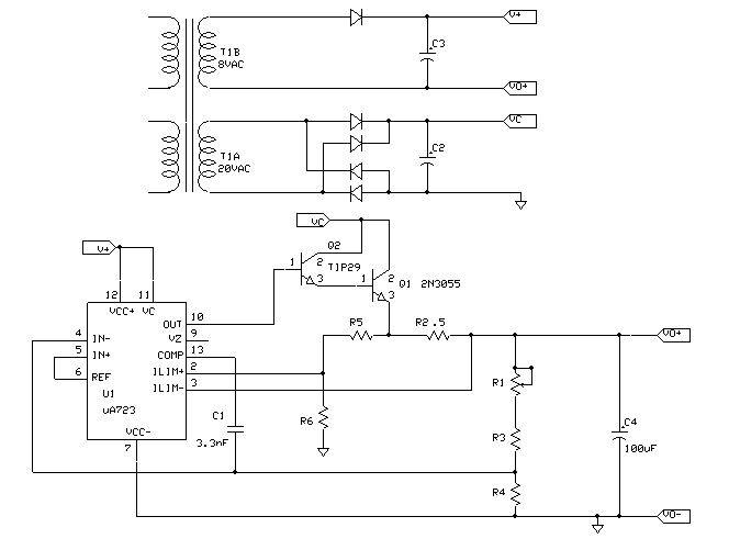
That's the start of a very good supply. Most of them had a LM723 IC to do the regulation. The current limit was usually a voltage divider. A pot can usually easily be hacked in to make an adjustable limit.
This one came with a trimmer for adjustment, I am just going to add leads and move it to the front panel using a regular full-sized part to do the job instead. I tried to read the writing on the IC again last night but got lost after LM, I think the maker tried washing it off with some chemical. I also have to get this thing working again, it died on power up last night after some preliminary testing. A little smelly but no smoke and no burns. We'll see what magic has managed to happen.
Dave Erickson's Electronics
Power-One Power Supply Hacker Page
Here is a simplified circuit of a Power-One supply. This is a +15V, 3A supply similar to the HC15-3.

Power-One Power Supply Hacker Page
Here is a simplified circuit of a Power-One supply. This is a +15V, 3A supply similar to the HC15-3.

That trimmer is likely for voltage adjustment. Some of these have a crowbar circuit that will shut them down if voltage climbs too high in case of a shorted output transistor. If you turned the trim pot up, that may be why it won't power up.
I have made no adjustment to the pot since I got it, it has been set at 12.8v. I just noticed the pot is labeled "v. adj" and made my assumption from that.
Dave Erickson's Electronics
Power-One Power Supply Hacker Page
Here is a simplified circuit of a Power-One supply. This is a +15V, 3A supply similar to the HC15-3.
Thank you for the link, excellent information.
In that circuit R5 would be the the resistor to change to a pot for an adjustable current limit.
Thank you for the info.
- Status
- This old topic is closed. If you want to reopen this topic, contact a moderator using the "Report Post" button.
- Home
- Design & Build
- Equipment & Tools
- New bench power supply