That looks right, but I am not an expert on noise.@AndrewT
Is this properly?
If my coefficient is 1.1
3.62mVrms/1.1 = 3.29mVRMS
3.29mVrms/10000 = 329nVrms (Referred to Input) ?
Can someone else confirm? Do we divide the measured value by 1.11, (I think we divide the measured result to allow for the over-read that the non brickwall allows).
or do we multiply the measured value by 1.11?
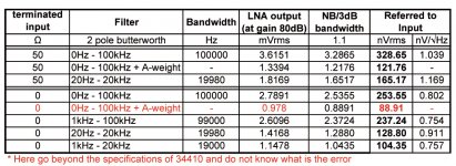
Table post15
the last column looks wrong.
The conversion from Vac to nVac is correct.
Now divide by the sqrt(100000) to give the nV/rtHz.
1.08 should be 1.14nV/rtHz
and divide by sqrt(20000)
1.22 should be 1.16nV/rtHz
Last edited:
I think we should то divide. As the filter slope is small so bandwidth wide. Wide bandwidth - great noise. See the link- relationship between Noise Bandwidth and 3dB Bandwidth for Butterworth Filter (page 101).
Data Conversion Handbook - Google
Table post15
the last column should be properly.
My mistake was that I did not explain. Excuse me for that. In the last column also considered and coefficient 1.11.
EnV (sqrt / Hz) = Vrms / SQRT (bandwidth*1.11)
EDIT Or perhaps more correctly is that:
EnV (sqrt / Hz) = (Vrms/1.11) / SQRT (bandwidth)
because the real noise at that filter is greater than the measured by coeff. 1.11
Last edited:
Excellent work. And quite a lot of work. measuring noise with a spectrum analyzer is difficult when you don't know the noise bandwidth if the filter. The correction factors become pretty involved quickly. I'm lazy, I have an FFT analyzer that does the corrections internally for me and reads out in noise density rtHz. I think that is a missing feature in the ARTA etc. software.
Another more realistic way to verify the input referred noise is to shunt the input with a variable resistor (for this 100 max) and increase its value until the noise (ideally measured narrow band at the target frequency) increases by 3 dB. This should have the equivalent noise of about 10 Ohms if its .3-.4 nV/rtHz. (I use this calculator Noise calculation calculator calculate Thermal noise Johnson noise white voltage level Nyquist dBu dBV signal-to-noise ratio S/N temperature bandwidth noise figure - sengpielaudio Sengpiel Berlin and set the bandwidth to 1 Hz) At that resistance the resistor is contributing the same noise as the preamp. Then look up the noise that value of resistor would generate at room temperature. This trick comes from the Quan-Tech transistor noise analyzer manual and it works pretty well.
The biggest challenge to building the William's low noise preamp http://cds.linear.com/docs/en/application-note/an124f.pdf (this is similar to the one he published) is the coupling cap. His big tantalum is unobtanium. Do the silmic etc. caps have as low an added noise?
@1audio
Many thanks for your clarification about the noise. Will be helpful for me.
Here's the table considering the coefficient.
Let someone with more experience to say - is that correct or not?
Many thanks for your clarification about the noise. Will be helpful for me.
I tried many high-end capacitors (audio only). There is no real difference in the measured results.... Do the silmic etc. caps have as low an added noise?
Here's the table considering the coefficient.
Let someone with more experience to say - is that correct or not?
Attachments
Last edited:
EDIT Or perhaps more correctly is that:
EnV (sqrt / Hz) = (Vrms/1.11) / SQRT (bandwidth)
because the real noise at that filter is greater than the measured by coeff. 1.11
I made a mistake. Should be:
because the real noise at that filter is less than the measured by coeff. 1.11
You are doing well, especially considering the language barrier. I'm hopeless outside of English.
I think adding the internal filters to the measurement process will lead to some confusion in the calculations. This is why I use the input resistor trick. It takes all these variables out. Have you verified the bandwidths and corner frequencies to make sure they are as designed? The response limitations of the HP34401 need to be considered as well. It does not use a real thermal converter and may not be accurate on noise with a higher crest factor. Measuring noise turns out to be much harder than it looks. You may need to measure the levels with the meter ranged up one level from the autorange to get accurate readings.
I think adding the internal filters to the measurement process will lead to some confusion in the calculations. This is why I use the input resistor trick. It takes all these variables out. Have you verified the bandwidths and corner frequencies to make sure they are as designed? The response limitations of the HP34401 need to be considered as well. It does not use a real thermal converter and may not be accurate on noise with a higher crest factor. Measuring noise turns out to be much harder than it looks. You may need to measure the levels with the meter ranged up one level from the autorange to get accurate readings.
Hi Demian,
You're right. This is not a exceptionally accurate measurement of noise. I just want to say that I measure with 34410A. Not 34401A. Differences in the two models in the RMS are big. Especially in the field of few mV. I have Ballantine 1395A thermal converter (1Vrms). It's accurate to 0.01 - 0.02%, but It requires at least 500mVrms.
When I have time I will use your "the input resistor trick". I will verify the bandwidths and corner frequencies of filter too. Thanks for the advices.
The biggest challenge to building the William's low noise preamp http://cds.linear.com/docs/en/application-note/an124f.pdf (this is similar to the one he published) is the coupling cap. His big tantalum is unobtanium. Do the silmic etc. caps have as low an added noise?
Silmic is not suited very well for this task. For low leakage capacitor check Nichicon KL series.
Wet tantalums can be found cheap at surplus stores or Ebay.
Attachments
I did not find any issues with "normal" foil capacitors in the audio range,
not even with good quality 50V X7R. That may be different for << 1 Hz,
which is not important to the audio people here.
That was in this amplifier:
< http://www.hoffmann-hochfrequenz.de/downloads/lono.pdf >
regards, Gerhard
not even with good quality 50V X7R. That may be different for << 1 Hz,
which is not important to the audio people here.
That was in this amplifier:
< http://www.hoffmann-hochfrequenz.de/downloads/lono.pdf >
regards, Gerhard
Silmic is not suited very well for this task. For low leakage capacitor check Nichicon KL series.
...
Especially for tests I order from digikey UKL1H101KPD. This is Nichicon 100uF/50V Low Leakage Cap (KL series). There is no difference in the measurement of noise. I used Silmic II for its low THD. It turns out that this capacitor (C12) has no practical(measurably) influence of noise.
I did not find any issues with "normal" foil capacitors in the audio range,
not even with good quality 50V X7R. That may be different for << 1 Hz,
which is not important to the audio people here.
...
Congratulations Gerhard. Impressive results.
About X7R. To measure the noise of power supplies may be appropriate. My amplifier is used for various activities. Including the audio. Therefore, the use of X7R in signal path is undesirable due to the high THD + N.
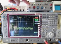
Personally to me with a spectrum analyzer measurements gave incorrect results.
This may be due to my the unfamiliarity of work with them. For first time I have access to a real analyzer. That is what I measured. See at the noise floor.
Almost -60dBm at output. At the output of the LNA is formed divider of 2 with 50ohms input of analyzer, so that real: -54 dbm. This is at 80 db gain and 50ohms terminated input. This means that on the input I have -134dbm (ref. 50ohm). This is 147dBV or 45nVrms. This result is far from the truth, so I do not post it before. To me, closest to the truth are the measurements with Agilent 34410A.
Attachments
Last edited:
Gnomcat,
Congratulations from me too, real nice work.
As for the spectrum analyzer: I don't think it lies to you..
On the screen you show the settings: you measure ~-60dBm noise floor with 2kHz resolution bandwith. Your logic then seems to be right, so you arrive at a floor (at the input! and at 2kHz RBW!) of -134dBm.
Now you have to normalize this for 1Hz resolution bandwith, that goes by the square root of the bandwith, 2kHz in our case: Sqrt 2000 is ~45, that is 33dB.
Because of the 2kHz wide open filter you collect this much more energy in each bin in the floor. So you have to subtract it from the measured value.
So your real 1Hz floor is (-134-33) dBm = -167dBm.
If you convert it back to tension, that is ~1nV/sqrt Hz input referred, which is what you had shown before?
In other words, your amp shows -167dBm excess noise above the -174dBm noise floor, that is having 7dB noise figure.
George
Joseph K,
Thanks a lot for your very precise explanation. I understood you completely. I learned something new from you") . I calculated the result by your explanations and really gets around 1nV/sqrt Hz (0.95). I did not make measuring at input terminated short (0ohm), because the results seemed to me abnormal.
. I calculated the result by your explanations and really gets around 1nV/sqrt Hz (0.95). I did not make measuring at input terminated short (0ohm), because the results seemed to me abnormal.
Thanks a lot for your very precise explanation. I understood you completely. I learned something new from you
. I calculated the result by your explanations and really gets around 1nV/sqrt Hz (0.95). I did not make measuring at input terminated short (0ohm), because the results seemed to me abnormal.Hi gnomcat, I like your implementation of a noise amp/RMS meter. This looks like a lot work and am still absorbing it. Your boards look quite nice to me, especially for home-made. I have been planning for too long, to make the x1, x10, x100, x1K gain RMS circuit in figure 10 of the first reference LT app note, (AN106), but have only recently started working on a layout. The parts sitting in desk waiting.. I especially like your panel layout controls and indications. Thank you for posting this impressive project. It is inspiring to me.
Michael
Michael
- Status
- This old topic is closed. If you want to reopen this topic, contact a moderator using the "Report Post" button.
- Home
- Design & Build
- Equipment & Tools
- My implementation of Ultra Low Noise Preamplifier and RMS Meter