Emm... no.
They call it 90 degrees, but this never happens in the real world, kinda. It is sought for, to be able to tune the PLL_F close enough to DUT_F to get diff signal within ADC BW.
If it tracks 100% 90 degrees, then mixer outputs zero, therefore there is no PN.
As far as i understand")
Look at these PLLs used in measurement equipment. They are quite broadband. We don't need wide tuning range for audio clock frequencies.
I found this doc,
http://dspace.cc.tut.fi/dpub/bitstream/handle/123456789/6660/rajala.pdf?sequence=3
Page 41 shows actual FFT of beat frequency ,centered at 55kHz.
They call it 90 degrees, but this never happens in the real world, kinda. It is sought for, to be able to tune the PLL_F close enough to DUT_F to get diff signal within ADC BW.
If it tracks 100% 90 degrees, then mixer outputs zero, therefore there is no PN.
As far as i understand
Look at these PLLs used in measurement equipment. They are quite broadband. We don't need wide tuning range for audio clock frequencies.
I found this doc,
http://dspace.cc.tut.fi/dpub/bitstream/handle/123456789/6660/rajala.pdf?sequence=3
Page 41 shows actual FFT of beat frequency ,centered at 55kHz.
There are techniques for measuring with the difference a low audio frequency. I think its called something like DMTD. You need a huge dynamic range to use it however, if the noise floor is in the -150 dB plus level. Its usually used to look at Allen Variance stability.
Here is the standard text on measuring with pretty complete instructions: Techniques for Measuring Phase Noise You can substitute a low noise opamp (AD797, LME49990) for the jFET amp and not lose much performance. Make sure the DBM is properly terminated and low pass filtered.
Here is the standard text on measuring with pretty complete instructions: Techniques for Measuring Phase Noise You can substitute a low noise opamp (AD797, LME49990) for the jFET amp and not lose much performance. Make sure the DBM is properly terminated and low pass filtered.
They call it 90 degrees, but this never happens in the real world, kinda. It is sought for, to be able to tune the PLL_F close enough to DUT_F to get diff signal within ADC BW. If it tracks 100% 90 degrees, then mixer outputs zero, therefore there is no PN.
Of course the PLL bandwidth is usually very low, below the lowest offset frequency of interest (although there are techniques to compensate the low-frequency effect of the PLL).
With basic phase detectors (e.g. double balanced mixer), the sensitivity to phase noise is highest, and to amplitude noise lowest, if the signals are in quadrature (and vice versa for the in-phase condition). For a free-running condition, the test setup invariably changes from measuring phase noise to amplitude noise. The DMTD technique Demian mentiones probably compensates the resulting effect mathematically (perhaps with the assumption that amplitude noise is much lower than phase noise (which is valid for most oscillators, in particular those with CMOS output)), but for a DIY setup the PLL method seems much easier and safer.
Some more reading:
Phase Noise Measurement: Phase Detectors
www.home.agilent.com/agilent/redire...IAL&ckey=1896487&lc=eng&cc=US&nfr=-35185.0.00
Samuel
I found the DMTD info. Here is a detailed intro: http://cdn.intechopen.com/pdfs-wm/24305.pdf It more for measuring frequency with very high resolution athan looking at phase noise but phase is preserved so it may allow phase noise measurements with very high resolution. Its effectively a variation on the cross correlation technique. http://www.holzworth.com/Aux_docs/Holz_MWJ_TechFeat_Feb2011.pdf HPw added the cross correlation to his analyzer software HpW-Works so with two reference oscillators you can measure below the noise floor of either. The setup to do this right will get more complex. The minicircuits phase detectors are optimized for this service Phase Detectors - Mini Circuits There are others that may be better but way more money.
At one point I started to lay out a PCB for this but the many different packages for oscillators and the less than clear impact of phase noise once its below the noise of the DAC/ADC suggest more was to be found in the audio output of the device. I may still make one for sorting oscillators. A test socket for the surface mount oscillators is a PITA to resolve. They do not have common footprints.
At one point I started to lay out a PCB for this but the many different packages for oscillators and the less than clear impact of phase noise once its below the noise of the DAC/ADC suggest more was to be found in the audio output of the device. I may still make one for sorting oscillators. A test socket for the surface mount oscillators is a PITA to resolve. They do not have common footprints.
I have a couple of days this nice digital generator.
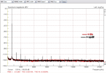
As a digital generator is very well. Here are some captures from an ES9023 based dac (THD, Jitter). They present two captures from either spdif or i2s input, the analogue to digital capture was done by EMU0404 (usb) with a 10K ladder attenuator.
I have attached another Jitter measurement from the same dac but the role of digital generator had a CMedia 6631A usb->i2s card.
As you can see the Altor JKGEN 384_12 has cleared jitter presentation.
Alex, I found the encoder very sensitive (J26), many times it jumps 2-3 click until one. What type is and I will appreciate if there is equivalent more precisely encoder in the market.
Attachments
Last edited:
4 June 2014: a new firmware released: Downloads - ALTOR AUDIO
Ver 3.4.07:
Ver 3.4.07:
- Impulse Test Added
- CrossSample Test Added
- Sine Squared Signal Added
- Frequency Sweep improved
- Digital Attenuation improved (0..-20dB 1dB step, -20..-90dB 10dB step)
if its a regular encoder, you can debounce with an RC filter. better to combine hw debouncing and sw debouncing, but if the code is not open, then hw debounce is all you can do. try a .1 or .01 cap and try various resistors (or even none). search controller forums (like arduino) for examples since this problem comes up frequently.
New waveforms tests
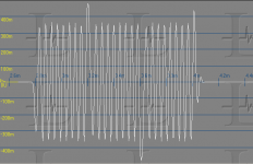
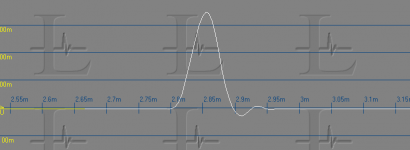
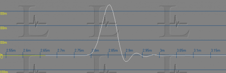
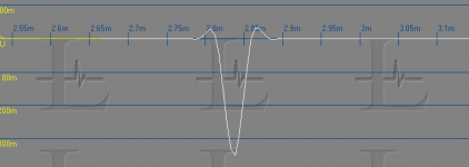
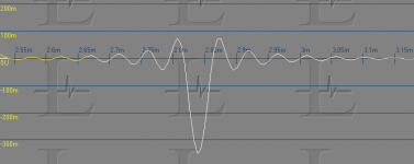
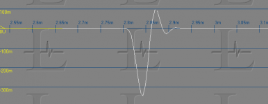
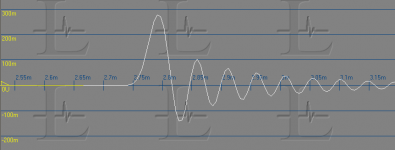
Here are some captures of the new waveforms using different filter options (AK4414 for the filter details short delay vs. normal and fast vs slow rolloff). The impulse tests are with a single sample pulse at full amplitude all at 44.1 KHz and captured at 192 KHz to not lose much detail.
First the impulse test, it will "violate" Nyquist in that it will have frequency content not possible to encode with an appropriate bandlimit. Essentially a recording should never have that encoded. The next waveform, sine squared (or raised cosine http://www.tsc.uc3m.es/~mlazaro/Docencia/DC/English-DC-T2-04-Raised_cosine-2p.pdf) is a valid waveform with the out of band info reduced (by 60 dB at least) so it can be recorded (which I did to show what the waveform is). Ringing on an "impulse" is not really valid but ringing on the sine squared would be an artifact worth understanding. Finally is the "cross sample" wave which is a burst with a 180 degree phase shift in the middle. This also is not valid with an infinitely fast change but it shows how some different filter solutions handle issues.
Some DACs actually clip on some of threse tests, it because the internal filter does not take into account the peaking of the low pass filter.
Attachments
-
 Cross Sample.PNG43.9 KB · Views: 73
 -
 Sine Squared SD+Slow 44.1.PNG12.6 KB · Views: 71
 -
 Sine Squared SD+ fast 44.1.PNG12.1 KB · Views: 62
 -
 Impulse Slow 44.1.PNG10.2 KB · Views: 70
 -
 Impulse fast 44.1.PNG14.9 KB · Views: 78
 -
 Impulse SD+Slow 44.1.PNG11.4 KB · Views: 250
 -
 Impulse SD+ fast 44.1.PNG16.5 KB · Views: 255
Here are some captures of the new waveforms using different filter options (AK4414 for the filter details short delay vs. normal and fast vs slow rolloff). The impulse tests are with a single sample pulse at full amplitude all at 44.1 KHz and captured at 192 KHz to not lose much detail.
First the impulse test, it will "violate" Nyquist in that it will have frequency content not possible to encode with an appropriate bandlimit. Essentially a recording should never have that encoded. The next waveform, sine squared (or raised cosine http://www.tsc.uc3m.es/~mlazaro/Docencia/DC/English-DC-T2-04-Raised_cosine-2p.pdf) is a valid waveform with the out of band info reduced (by 60 dB at least) so it can be recorded (which I did to show what the waveform is). Ringing on an "impulse" is not really valid but ringing on the sine squared would be an artifact worth understanding. Finally is the "cross sample" wave which is a burst with a 180 degree phase shift in the middle. This also is not valid with an infinitely fast change but it shows how some different filter solutions handle issues.
Some DACs actually clip on some of threse tests, it because the internal filter does not take into account the peaking of the low pass filter.
Thank you, Demian. Good demo/info. THX-RNMarsh
Hello friends,
I put an "errata sheet" to the website.
Direct link: https://drive.google.com/file/d/0B1TjbYphHfS5ZGFURDk3VFNhT0E/edit?usp=sharing
Actually to all devices, with Main PCB revision 1.3 and 1.3a.
(Before making these modifications, please check - may be your board are already modified!)
I put an "errata sheet" to the website.
Direct link: https://drive.google.com/file/d/0B1TjbYphHfS5ZGFURDk3VFNhT0E/edit?usp=sharing
Actually to all devices, with Main PCB revision 1.3 and 1.3a.
(Before making these modifications, please check - may be your board are already modified!)
Hi Lemon,
I think you have PCB Ver. 1.3A (not need this mod) or 1.3 with mod made by myself.
I just update the file at website.
Attention - I've deleted the old file, so the link in the previous message does not works.
Go to http://www.altor.co/downloads
I think you have PCB Ver. 1.3A (not need this mod) or 1.3 with mod made by myself.
I just update the file at website.
Attention - I've deleted the old file, so the link in the previous message does not works.
Go to http://www.altor.co/downloads
Attachments
Last edited:
You have right, mine is 1.3A
But, there isn't any continuity between pin3 & pin1. Is that OK.
For mine situation (pcb 1.3A), must to proceed only with "2. Internal MCLK is not always stable at 48/96/192/384 kHz.", isn't it? I don't see any wire jumper btw c5 & c38 and the routing at the opposite isn't cutting.
But, there isn't any continuity between pin3 & pin1. Is that OK.
For mine situation (pcb 1.3A), must to proceed only with "2. Internal MCLK is not always stable at 48/96/192/384 kHz.", isn't it? I don't see any wire jumper btw c5 & c38 and the routing at the opposite isn't cutting.
You have right, mine is 1.3A
But, there isn't any continuity between pin3 & pin1. Is that OK.
For mine situation (pcb 1.3A), must to proceed only with "2.
Yes, for 1.3a it is already connected at another place.
Internal MCLK is not always stable at 48/96/192/384 kHz.", isn't it? I don't see any wire jumper btw c5 & c38 and the routing at the opposite isn't cutting.
If you do not see any problem at 48x scale, you may leave it.
20 Sept 2014: a new firmware released: Downloads - ALTOR AUDIO
Ver 3.4.09 (based on 3.4.08beta):
Ver 3.4.09 (based on 3.4.08beta):
- ConstValue signal added to DoP/DSD Modes
- DSD Shapes: 1002Hz Triangle and Square Waves, -3dB
- DSD Shapes: 441, 1002, 11025, 22050 and 44100 Hz Sine Wave, -3dB
- Pink Noise processing improved, now no 94kHz Fs limit
- LF Frequency Mode (1mHz-1kHz) added
- Frequency set changed from "Pos/Fix" to "Pos/Fix/LF"
- Channel switch:
was: L+R in-phase, L-R out of phase, Left only, Righ only, Mute
added: LxR Orthogonal signals (90 degree phase shift) - Dig. Attenuation accuracy improved
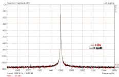
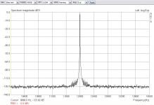
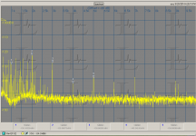
Here is a quick test of the new firmware (but not a new feature). Thsi is the AKM AKD4490 demo board connected to the JK1 via I2S running at 352.8 KHz sample rate -3 dBFS 1 KHz. The signal was routed through a Shibasoku 725 to remove the fundamental and scale the output. The distortion out was coupled to an EMU 1616M Line in adjusted for sensitivity and scaling in Praxis to get the correct output scaling of the distortion.
I will attempt the DSD setup but that gets really complicated since the demo board needs to be programmed via a USB port and program. Its quite involved and I may not be able to get everything to line up. The chip supports 1X, 2X and 4X DSD so it has a lot of things to tweak to get it working right.
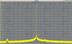
Also is a plot of the Jtest test at 44.1 over I2S. It probably would not show anything since there would only be the master clock to induce jitter and with everything synchronous not much is likely to show up. Still the only sidebands are at -120 dB. They at approx 120 Hz from the fundamental suggesting power supply modulation of the master clock.
I will attempt the DSD setup but that gets really complicated since the demo board needs to be programmed via a USB port and program. Its quite involved and I may not be able to get everything to line up. The chip supports 1X, 2X and 4X DSD so it has a lot of things to tweak to get it working right.
Also is a plot of the Jtest test at 44.1 over I2S. It probably would not show anything since there would only be the master clock to induce jitter and with everything synchronous not much is likely to show up. Still the only sidebands are at -120 dB. They at approx 120 Hz from the fundamental suggesting power supply modulation of the master clock.
Attachments
- Status
- This old topic is closed. If you want to reopen this topic, contact a moderator using the "Report Post" button.
- Home
- Design & Build
- Equipment & Tools
- Low Frequency Analog and Digital Signal Generator