 .
.Hi Altor,
If understood well, the only difference btw the ready "JKGEN 384-12" and the 4-kit "JKGEN 384-12 Kit" is the case, cables and front rca's and others?
Then the "JKGEN 384-12 DIY Kit-2" is including everything but non assembled (except case, cables and front rca's and others)?
If understood well, the only difference btw the ready "JKGEN 384-12" and the 4-kit "JKGEN 384-12 Kit" is the case, cables and front rca's and others?
Then the "JKGEN 384-12 DIY Kit-2" is including everything but non assembled (except case, cables and front rca's and others)?
Hi Altor,
If understood well, the only difference btw the ready "JKGEN 384-12" and the 4-kit "JKGEN 384-12 Kit" is the case, cables and front rca's and others?
Yes.
Then the "JKGEN 384-12 DIY Kit-2" is including everything but non assembled (except case, cables and front rca's and others)?
It also does not includes resistors, capacitors, connectors, and other "not so important components".
Only Main PCB + Output&DAC PCB + FrontPanel PCB + IC + TFT +Encoder + Clock PCB (assembled).
P.S. All the prices at the site www.altor.co are temporary, and can be changed in the future.
Thanks for the answering.
At the JKGEN 384-12 Kit the components are soldering?
At "Kit" - yes, at "Kit-1" and "Kit-2" - no.
I have been meaning to post some measurements but two thinks happen everytime I start. First, I find that the limits are the DAC I'm testing. Second, that I can find some small tweaks to the measurements to get better results, but they are all at the DAC side. The generator is essentially "perfect" and anything you measure is in the DAC.
I'll try to illustrate this soon.
I'll try to illustrate this soon.
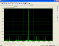
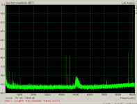
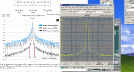
JTest measurement example
Here are two Jtest measurements using the JK generator's Jtest as a source over coax spdif into the demo board for the ESS9018 mobile version. On the 24 bit version the 1 bit modulation at 24 bits is lost in the noise (not really a 24 bit DAC but none are) and the 1 bit modulation is clearly visible on the 16 bit version. There are no clear jitter artifacts in either plot.
The JK source is essentially perfect in this set of plots (and any departures from perfect are in the DAC).
I'm set sort of the same as the jitter plots in Stereophile reports. They are not identical because the AP digitizer does not run at an audio sample rate. They should be similar however.
Attachments
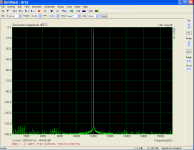
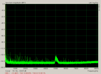
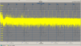
Another Jtest
Here is another Jtest, this time for an AKM AKD4414 demo board. Its very similar, except you can see a little modulation on the sidebands adjacent to the carrier.
This uses the AK4118 as the line receiver.
This is where I start exploring the cause etc. and get nothing done. . .
Here is another Jtest, this time for an AKM AKD4414 demo board. Its very similar, except you can see a little modulation on the sidebands adjacent to the carrier.
This uses the AK4118 as the line receiver.
This is where I start exploring the cause etc. and get nothing done. . .
Attachments
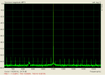
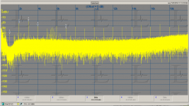
THD measurement
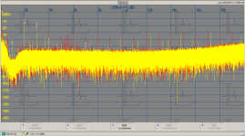
This is the THD of the AKD4414 board at 0dBFS or max out. This is a worst case point for many DACs. Again the distortion measures to .00026%. The THD+N is limited by the 100 KHz band of the measurement and the lower input level on the EMU1616m I'm using. At the -10 setting the EMU is clipping so I'm using +4 and the signal is about 12 dB below full scale on the EMU input.
This is the THD of the AKD4414 board at 0dBFS or max out. This is a worst case point for many DACs. Again the distortion measures to .00026%. The THD+N is limited by the 100 KHz band of the measurement and the lower input level on the EMU1616m I'm using. At the -10 setting the EMU is clipping so I'm using +4 and the signal is about 12 dB below full scale on the EMU input.
Attachments
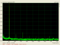
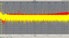
Another distortion spectrum
This shows the same AKD4414 running at 44.1 but the full 100 KHz spectrum of the capture system is shown. at the center you can see the images of the 1 KHz and the 44.1KHz sample clock leaking through at -90 dB. This is normal and pretty good rejection (-90 dB in one octave). With a non-oversampling DAC and no low pass filtering those would be at full scale. Most tweeters don't like that much ultrasonic energy.
This shows the same AKD4414 running at 44.1 but the full 100 KHz spectrum of the capture system is shown. at the center you can see the images of the 1 KHz and the 44.1KHz sample clock leaking through at -90 dB. This is normal and pretty good rejection (-90 dB in one octave). With a non-oversampling DAC and no low pass filtering those would be at full scale. Most tweeters don't like that much ultrasonic energy.
Attachments
Distortion
Last one for now-
same plot except switching the sample rate of the source to 192 KHz.
997 Hz is used to make sure its not synchronous to any clocks in the system. That will ensure that every bit is exersized over time on reproducing the sine wave. Any errant bits will produce distortions. Its still showing .00035% which is really low. The junk around 50 KHz is in the EMU box and did not change when i changed the same rate.
The Generator is a breeze to use to do these tests.
Attachments
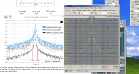
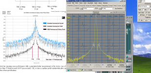
Another interesting measurement
I thought I would try to compare this setup with the measurement of the MSB Femtoclock (a really extravagant clock option): Femtosecond Galaxy Clock . I tried a number of ways to duplicate the measurements they show on the web site.
I used three window functions with the JK as the source running at 48K and the capture system at 192K. I used 4X the samples to correct for the 4X sample rate to get the same frequency resolution (bin size) and noise floor.
What is interesting is that the sidebands in the worst case are better than the "Femtoclock" and suggest a jitter of something close to 15 fS over SPDIF. I think this calls the measurement into question more than anything but clearly the jitter of the JK generator is really low.
Its also interesting to see how much the window affects the measurement. In this case we are looking between the signals. If you are looking at the peak values different window functions would be preferred.
Attachments
1audio many thanks for these marvelous information with measurement captures of this digital generator.
I appreciate it and already I have pre-order this.
Can you give me a more information about "I used 4X the samples to correct for the 4X sample rate to get the same frequency resolution (bin size) and noise floor. "
What is the final samples that you used?
Are there any rules about the relation of bit depth/Resolution/Samples?
For example, I have seen that if you captured a signal (JTest for example) with 24bit/48KHz/16K samples and then change the samples to 2X or 4X (with the same bit and resolution) the noise level is decreased.
I used ARTA software, at the manual there is no any information about this, except that to JTest suggests Hanning Method.
Think of it this way-
If you have uniform spectral density (white noise) in a spectrum from 0-24000 Hz and divide it into 8192 parts each part will have the same energy. If your measured spectrum is 0-96000 and you divide it up into 32768 parts each part will have the same as 1/8192 of 0-24000. This is what I meant by resolution.
If you have uniform spectral density (white noise) in a spectrum from 0-24000 Hz and divide it into 8192 parts each part will have the same energy. If your measured spectrum is 0-96000 and you divide it up into 32768 parts each part will have the same as 1/8192 of 0-24000. This is what I meant by resolution.
Some more DAC distortion measurements
Since it was all set up I decided to measure the distortion of the two highest performance DAC's I had immediately available.
There were all measured through the Shibasoku 725D. The distortions are so low that the ADC (AK5394A) would be limiting is seeing the real distortions. There are two plots for each DAC, first without the 20 KHz filter in the 725D, second with. The filter is used to remove high frequency junk that can degrade the measurement. However it brings its own degradation in both distortion increase and noise. Two things I'll be exploring soon.
The ESS 9018 mobile has become popular in some very premium mobile devices. I'm measuring its demo board and the AKD 4414 demo board. They are for very different applications. The AK4414 has 4 outputs and a large footprint and not really mobile friendly.
You can see the difference in the performance in that the AK4414 harmonics decay nicely and quickly where the ESS9018 harmonics are low but do not decrease with frequency. The 0 line is -100 dB so all of these distortions are very low.
These are all at -6 dBFS 48 KHz on the JK generator spdif in.
Attachments
-
 ESS 9018 mobile distortion spectrum via 725d.PNG79.2 KB · Views: 115
 -
 ESS 9018 mobile distortion spectrum via 725d w 20 KHz filter.PNG74.6 KB · Views: 97
 -
 AK 4414 distortion spectrum via 725d wo 20 KHz filter (ESS in red).PNG86.9 KB · Views: 93
 -
 AK 4414 distortion spectrum via 725d w 20 KHz filter (ESS in red).PNG92.7 KB · Views: 83
I like a much this generator!
1audio, can you take some basic measurements of analogue output? I know that is digital generator mainly, but it is an option with interesting!
altor, what kind of dac-chip you used at the dac-board of generator? Do you thinking some boards to be upgradable to the future? For example a better DAC board...
- Status
- This old topic is closed. If you want to reopen this topic, contact a moderator using the "Report Post" button.
- Home
- Design & Build
- Equipment & Tools
- Low Frequency Analog and Digital Signal Generator