I think you will have fabricate your own cables. I can provide specific help in PM if you wish.
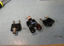
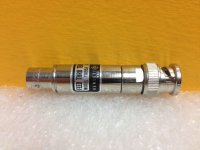
But this should get you started. The 600 ohm load you refer to is Part # HP11095a and is available on the big auction site. It has bnc male/female connectors on each end. At that same site you can pick up a variety of connectors like a "dual banana to bnc female". A cheaper alternative to the HP11095a load would be to use a 600 ohm metal film resister mounted to set screws in one of the above mentioned connectors.
The display on your oscilloscope should be a near perfect sine wave. How do you have this connected? If all you have is a regular oscope probe then you can just use short piece of stiff wire in the HP339 Oscillator output connector. Or use a (dual banana to bnc) and a (bnc to bnc) cable to connect to your oscope.
Attachments
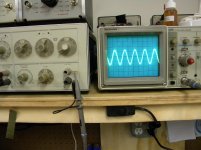
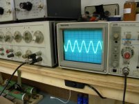
Actually further investigation: I get a clean sine wave at 1volt like you show but my .3 and .1 are completely dead. 30 mv is OK and 10mv and 3mv are extremely fuzzy and look like a triangular fuzzy signal.
What does your 10mv and 3mv look like? are they fuzzy also? The amp I would like to check has considerable gain and I'd like to check it with 10mv and 3mv.
BTW your 339a looks a lot better than mine. I have a 2215a scope similar to the one you have. Thanks for the info on the connectors.
What does your 10mv and 3mv look like? are they fuzzy also? The amp I would like to check has considerable gain and I'd like to check it with 10mv and 3mv.
BTW your 339a looks a lot better than mine. I have a 2215a scope similar to the one you have. Thanks for the info on the connectors.
What I used was Testors » Testors » Modeling Tools & Accessories » Decals » Decal Paper - Clear & White
but if you Google "Inkjet Prinatble Decal Paper" you will get tons of options. Basically, it is a sheet of clear paper that can be run through an inkjet printer (there are versions that work in laser printers too) so you can print whatever you want. Then a clear spray is applied over the printing to protect it. After that dries, you cut out the decal and soak it in water for a couple of seconds and that releases the paper backing, leaving a clear decal with the printing on it. You then slide this off the paper and onto whatever you want to apply it to.
As I said in my post, I did this because one of the knobs on my 339 was really messed up. The previous owner had tried to repair the knob and had gotten epoxy all over the back side of it and destroyed most of the lettering (which is on the back side of the knobs). So I sanded the back side completely smooth and then used finer and finer grades of emery paper until it was clear again. I finished with a plastic polish like you can get for automobile headlights or motorcycle windscreens. Then I printed the new numbers on the decal, but since I was placing the decal on the back side of the knob, I printed it in reverse. You can use any program you like to make the numbers. I just used Microsoft Word.
If your knobs are not in such terrible shape, then I would not use this method. One of my other knobs was had a few of the numbers missing because the black paint used for the lettering had be chipped away. To fix that, I used some black paint and carefully applied it with a toothpick. It didn't look too good, but after it dried a bit, I went back with a very sharp exacto knife and cleaned up the edges. A good magnifier is helpful for that.
They also make a dry transfer type of paper that lets you rub the letters off onto a panel :
Dry rub off decal paper - YouTube
Inkjet Rub-on decal paper transfer paper.
I haven't tried that.
Terry
Here is a dry transfer that leaves no carrier. Just the ink.
Custom DRY TRANSFERS and no-carrier DECALS in 5 minutes with "DecalPRO"
Again, I haven't tried this one, but they show an example of replacing all the lettering on an electronic equipment panel. It looks pretty nice.
Terry
Custom DRY TRANSFERS and no-carrier DECALS in 5 minutes with "DecalPRO"
Again, I haven't tried this one, but they show an example of replacing all the lettering on an electronic equipment panel. It looks pretty nice.
Terry
Can someone take a digital voltmeter and check the output from their 339A power supply? The output shows (ground to TP303 and ground to TP304) +15volts DC and -15Volts but I also get 3+volts AC which I think is bad. (ground to TP301 and ground to TP302) also shows AC as well as the +-15V DC. I think something must be leaking the AC through.
If you would like a schematic of your 339A ths link has huge (2 pages per dwg) and I printed them out and taped them together. Old eyes of mine can read them quite easily.
http://bee.mif.pg.gda.pl/ciasteczkowypotwor/HP/339a_6.pdf
http://bee.mif.pg.gda.pl/ciasteczkowypotwor/HP/339a_6.pdf
In this case I wouldn't expect the zeners to conduct under normal conditions. They are there just for protection from surges on the power line. If they conduct the fuse should blow. The normal voltage across the zener is probably about 40 volts or a little less. The zener would only conduct if the voltage rose to above 56 volts during a surge. They are there to protect the rest of the regulator circuitry from being damaged by surges.
Sometimes zeners are used as a voltage regulator, but in that case there would be a resistor in series with the zener to limit the current.
The waveform you should see on the zener will be DC (+20V on one side, -20V on the other), with a small amount of AC ripple (less than a volt).
Terry
Sometimes zeners are used as a voltage regulator, but in that case there would be a resistor in series with the zener to limit the current.
The waveform you should see on the zener will be DC (+20V on one side, -20V on the other), with a small amount of AC ripple (less than a volt).
Terry
I think you ae correct. This could happen if someone plugged the unit into a 240 line but had the switches set for a 120. I do see on the side between the transformer and rectifier a clipped sine wave. I think the resistor you reference to keep from blowing the fuse must be the windings on the transformer secondary. On the other side of the rectifier at the zener I see a smoothed voltage of +14.5v and -14.8v with some ripple. I still can't see however why the sine wave is clipped on both peaks. I'm beginning to wonder if the .1uf capacitor is failing.
The clipped sine is probably normal. It is caused by the bridge rectifier and transformer. Since the filter caps are mostly charged up, the bridge diodes and transformer only conduct current when the sine wave peak from the transformer exceeds the capacitor voltage by the 0.6 volt drop of the bridge diodes. During the time the diodes conduct, the current flows, causing a drop due to the transformer resistance and the diode resistance. This makes the sine wave look somewhat clipped.
Terry
Terry
- Status
- This old topic is closed. If you want to reopen this topic, contact a moderator using the "Report Post" button.
- Home
- Design & Build
- Equipment & Tools
- HP-339A Calibration