For daily use the Panasonic would be my first choice. A PC or tablet in the middle always slows things down. If you are documenting or need to make a complex set of measurements the PC/cloud types of stuff is great. To adjust bias on output transistors the smoke may get out before you know you went too far.
Also the Panasonic won't get damaged if something it wrong. The PC stuff will if it isn't fully protected.
Also the Panasonic won't get damaged if something it wrong. The PC stuff will if it isn't fully protected.
Thank you for the advice, soundcard/PC stuff isn't a good choice for a repair shop, but it took me some years to understand that an old Bruel Kjaer 1022 is the **** when you make repair job, also it took me some years to understand that an old good analouge oscilloscope is very useful instead of fiddling with PC display.
I have a lot of good old stuff but it is very frustrating to manage them togehter into a "audio measure station".
The Panasonic VP-7722A, how old are those instruments and it is some hard to get spare parts or parts that I should buy just now.
I have a lot of good old stuff but it is very frustrating to manage them togehter into a "audio measure station".
The Panasonic VP-7722A, how old are those instruments and it is some hard to get spare parts or parts that I should buy just now.
VP7722A
I used one of these from approximately -90 to 2005. It is a most competent analyzer, and one that you could probably live with for many years. It can even analyze down to the fifth harmonic just by pressing a button.
I far as I`m aware of it has no particular weakness, so I could`t advise on parts to stock. I still have my original service manual for it, however, where I have it I can`t say. To many relocations the last years.
Regards
Roar
Presados lords
I request to kindly inform me if have for sale a copy of the operating manuals and schematics and calibration devices listed below.
Looking forward to its manifestation
Automatic Distortion Analyzer Shibasoku 725 B
Multichannel TV Sound Signal Generator TA35C
grateful
Alvim
I request to kindly inform me if have for sale a copy of the operating manuals and schematics and calibration devices listed below.
Looking forward to its manifestation
Automatic Distortion Analyzer Shibasoku 725 B
Multichannel TV Sound Signal Generator TA35C
grateful
Alvim
I made a significant upgrade to my 725. I was bugged by a 2nd harmonic that was pretty strong (-120dB or so). After adjusting the input offset with no effect on the distortion I went to the next stage, the band elimination filter. On that board (A3) I first installed sockets on U1 and U2 and returned the original opamps with no success. At least it wasn't broken.
The I swapped the HA2625 in U1 with an LME49990 I had already mounted on a SOIC to DIP adapter. I was not expecting much but it did the trick. Now, with the Viktor oscillator as a source (the cleanest I have) I get -140 for the 2nd and less for all the others. Schematic for the band elimination filter board below.
The Shibasoku 590AR I have has not lent itself to an easy upgrade the same way. I shuffled the analog multipliers (socketed part) until I got the lowest distortion but I think it has more performance potential with a few parts upgrades. I expect I need to swap the input fets on the amp stages to matched pairs to get it working right. For now it has a limit at around -130 for the harmonics.
Attachments
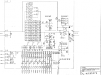
I made a significant upgrade to my 725. I was bugged by a 2nd harmonic that was pretty strong (-120dB or so). After adjusting the input offset with no effect on the distortion I went to the next stage, the band elimination filter. On that board (A3) I first installed sockets on U1 and U2 and returned the original opamps with no success. At least it wasn't broken.
The I swapped the HA2625 in U1 with an LME49990 I had already mounted on a SOIC to DIP adapter. I was not expecting much but it did the trick. Now, with the Viktor oscillator as a source (the cleanest I have) I get -140 for the 2nd and less for all the others. Schematic for the band elimination filter board below.
.
This is the same opamp used by HP in some of their gear and I found similar improvement when replaced by other newer opamps.
Thx-RNMarsh
It might be worthwhile to point out that the opamp which bootstraps the notch filter (QA2) does contribute to the distortion residual in a non-obvious way. While it does not see significant input or output voltage swing, its output sources significant AC current which in turn causes a distorted voltage to appear at the output terminal. Perhaps biasing the opamp into class A (see e.g. Tek SG505 schematic for a neat way to do this with a '5534) is useful here.
Samuel
Samuel
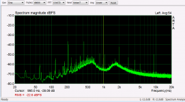
I saw that too and did socket the opamp. But when the distortion dropped basically into the noise I stopped fiddling. In the plot below the top of the scale is approx -100dB, the fundamental is -122dB and the second is at -142dB. I am not sure what will detune or otherwise alter the performance of the notch filters. The manual is completely devoid of alignment info. This is with Viktor's oscillator, which is the best source I have. I figured I would stop while I'm ahead.
Attachments
I saw that too and did socket the opamp. But when the distortion dropped basically into the noise I stopped fiddling. In the plot below the top of the scale is approx -100dB, the fundamental is -122dB and the second is at -142dB. I am not sure what will detune or otherwise alter the performance of the notch filters. The manual is completely devoid of alignment info. This is with Viktor's oscillator, which is the best source I have. I figured I would stop while I'm ahead.
Very

-RNM
It might be worthwhile to point out that the opamp which bootstraps the notch filter (QA2) does contribute to the distortion residual in a non-obvious way. While it does not see significant input or output voltage swing, its output sources significant AC current which in turn causes a distorted voltage to appear at the output terminal. Perhaps biasing the opamp into class A (see e.g. Tek SG505 schematic for a neat way to do this with a '5534) is useful here.
Samuel
Great helpful input !
Curious.... what would a dual opa in parallel here accomplish?
THx-RNMarsh
At best a 3 dB reduction in noise? Paralleling opamps on a chip can work. Yamaha did it in an FM tuner with good results. No improvement in distortion however.
Can you take a picture of the first band elimination filter board in the 725D? I may be able to figure out the board. The circuits have not changed much.
Can you take a picture of the first band elimination filter board in the 725D? I may be able to figure out the board. The circuits have not changed much.
The pcb are not labelled as such. Just a part number on them. There are no Harris opamps any more.... seems they all got changed to 5532 etal.
Can you put up the selectable filter circuit board for us? I think that part didnt change. Maybe I can reduce the S/N on the monitor output path.
-RM
Can you put up the selectable filter circuit board for us? I think that part didnt change. Maybe I can reduce the S/N on the monitor output path.
-RM
What would a dual opamp in parallel here accomplish?
As they share the output current a small reduction in distortion can be hoped for, but crossover distortion is a complex phenomena (over a limited range reducing the output current might increase distortion a bit) so this might not work that way in this particular instance.
I'm not sure if there is perhaps also a side effect from doing this--you need (small) output resistors to sum the outputs (otherwise the different offset voltages make the opamps fight each other), and that might interfere with the frequency response of the notch filter. But the effect is probably negligible.
Samuel

I have Richards 725D. Here are a few quick impressions:
Its really similar to the older units but redone from top to bottom. The boards have more functionality per board.
The key new features are the dual differential inputs etc. that allow testing a stereo source without swapping cables. It has an internal 20 KHz low pass filter probably to meet the EIA and JIS standards for testing digital amps with lots of ultrasonic junk. And it has a 2 mV distortion capability for measuring the dynamic range of a DAC per the standard tests.
Richards unit does have a noise problem, that my much older unit does not have. I think it relates to the post filter gain circuitry since its not real obvious in the analog outputs but I'm not sure yet.
The notch filter is different- instead of three boards of twin t filters there is one board with enough relays for three filters. However there are not enough opamps for three filters. I will need to do some reverse engineering to figure it out. It also has a stacked opamp that appears to be two cascaded opamps as a "fix". It still uses the open loop filter scheme of the older units, no servo for tuning.
Overall its pretty similar to the older design so reverse engineering what I need should not be really hard.
I'll try to post details as I dig into the beast.
- Home
- Design & Build
- Equipment & Tools
- ShibaSoku Automatic Distortion Analyzer