Likewise. But I don't have the skills nor the tools to pursue such a project myself.
I only have experience laying out circuit boards for analog circuits, not mixed signal like and ADC would require. I can fetch information off the internet though. I seem to be good at that.
This project will be exclusively the for purpose of measurement.
Just a high quality ADC stream. I will also look into forcing periodicity with the sampling. This would avoid the need for windowing the FFT. A first start approach to this would begin with synchronizing the beginning of the sampling with the zero crossing of the input sine.
I'll keep the boards modular so it's all plug and play.
Cheers,
OK, please let me know how I can support this project. I don't mind spending some money on it. Let me know.
The Amanero is an output adapter. Won't do us much good for an ADC.
The fpga could be reprogrammed. It all depends if Domenico (Amanero) would be interested in doing it and for which price/quantity. The drivers (output only ofc) supports DXD sampling rate and that would be a big plus vs other solutions IMO (same as via, but not sure the issues there).
Richard, of course we dont want to use the dirty USB power (one reason the 0404 is better than the 0202 it has a separate psu).
There's a lot of unused pins with this project. I can replace the PIC in my SVO design with the Atmel making a osc analyzer set. The Atmel is a better processor all around than a PIC.
I'd rather use something I can get into and make changes to rather than having to depend on someone else. The project is open source and modular. This means if something better comes along then rip out one board and replace it with another or connect through an open port.
I'd rather use something I can get into and make changes to rather than having to depend on someone else. The project is open source and modular. This means if something better comes along then rip out one board and replace it with another or connect through an open port.
USB brings lots of potential and challenges. The potential of sophisticated control is very attractive. The limited power and shared grounds do force a more involved approach to power design and management.
The AB1.2 has on it a clock chain designed to provide clocks for synchronizing charge pumps to the master clocks (for future work). However isolation will require transformers. The power limitation may be the biggest roadblock. USB2 is limited to 500 mA at 5V. Its possible to get more but many ports won't support more that this limit. this means a 2.5W power budget without a separate supply. I would prefer this so I am rid of another ground loop. The QA400 shows this potential. Especially with a laptop running on battery.
Another option is a second port for power for the analog circuitry (Like my adapter)
Borge let me know he us up for this project if there is enough interest that he can recoup his costs in getting a run of PCB's assembled. It would be all open source but chasing down some of the parts can be difficult. I think this will need to be surface mount multilayer to meet the performance goals. We are also discussing isolation for both power and data/clocking.
I think adding an ultra low distortion oscillator and a matched notch filter would enhance the performance limits to the range of the Shibasoku. This could be the most difficult part.
The ASIO in the Audio Widget project is a fresh from the ground up effort for the project.
Hi Guys,
I have been thinking about making something similar to this. But, the day job has been taking most of my time beside the family. Then I saw the QA400 and thought it was a great short-cut and is likely capable of doing most what I have the need for. Especially with Demians front end. However, this DIY and the next best is never good enough.
How fast does this project has to move? I'm an embedded SW guy although these days I program PC SW to mimic embedded environment and HW.
I would be glad to help out, if it can fit inot my spare time.
Best regards,
Mogens
Hi Guys,
I have been thinking about making something similar to this. But, the day job has been taking most of my time beside the family. Then I saw the QA400 and thought it was a great short-cut and is likely capable of doing most what I have the need for. Especially with Demians front end. However, this DIY and the next best is never good enough.
How fast does this project has to move? I'm an embedded SW guy although these days I program PC SW to mimic embedded environment and HW.
I would be glad to help out, if it can fit inot my spare time.
Best regards,
Mogens
Yes !!! Thx
USB brings lots of potential and challenges. The potential of sophisticated control is very attractive. The limited power and shared grounds do force a more involved approach to power design and management.
The AB1.2 has on it a clock chain designed to provide clocks for synchronizing charge pumps to the master clocks (for future work). However isolation will require transformers. The power limitation may be the biggest roadblock. USB2 is limited to 500 mA at 5V. Its possible to get more but many ports won't support more that this limit. this means a 2.5W power budget without a separate supply. I would prefer this so I am rid of another ground loop. The QA400 shows this potential. Especially with a laptop running on battery.
Another option is a second port for power for the analog circuitry (Like my adapter)
Borge let me know he us up for this project if there is enough interest that he can recoup his costs in getting a run of PCB's assembled. It would be all open source but chasing down some of the parts can be difficult. I think this will need to be surface mount multilayer to meet the performance goals. We are also discussing isolation for both power and data/clocking.
I think adding an ultra low distortion oscillator and a matched notch filter would enhance the performance limits to the range of the Shibasoku. This could be the most difficult part.
The ASIO in the Audio Widget project is a fresh from the ground up effort for the project.
HI Demian,
AD have galvanic isolators for I2C and ever other kind of digital interface. USB is limited and of no use here. Even the master clock can be isolated with these. AD a has an inexpensive line of these where GND isolation is of interest. These have a lower potential isolation of 1kV. All of this can go on the Audio IO boards ADC/DAC.
I need at least 16 free GPIO pins plus the SPI. If need be I can do this through an SPI GPIO expander. Microchip has some small expander with decent output supply current which can drive relays directly. Speed of control is not an issue. I have four MDac's that need to be loaded for OSC tuning. The tuning Dac's are in two parallel sets. It would nice to be able to offset the MDac pairs for fine tuning but this requires more CS lines. Output attenuation will be handled by relays and an attenuation network. I would rather not have any pots involved. Four more lines are needed for range setting. Output level detection will need one line for the uP's 10bit ADC. The design also has a frequency counter which displays on the GUI.
I have no idea how much room is left in the Widgets in terms of program memory, processing power and time on the USB. I need at least one in and one out USB EP.
Frequency counting runs in the timer modules independently but overflows and time need to be captured and this requires an interrupt. The timing will be tricky since I cant interfere with the sending or receiving of data packets on the USB.
Cheers,
Hi David,
I have a audiowidget here. I bought one as I thought they had switched to the ATMEL Cortex M3 type used on the Amanero board, of which I also have two on the way. I have no idea if the ATMEL has more processing power than the ARM M3, other than I like ARM processors. But, I don't have a preference.
My napkin schematic include optical galvanic isolation and FPGA on the ADC/DAC side.
Best regards,
Mogens
Hi Guys,
I have been thinking about making something similar to this. But, the day job has been taking most of my time beside the family. Then I saw the QA400 and thought it was a great short-cut and is likely capable of doing most what I have the need for. Especially with Demians front end. However, this DIY and the next best is never good enough.
How fast does this project has to move? I'm an embedded SW guy although these days I program PC SW to mimic embedded environment and HW.
I would be glad to help out, if it can fit inot my spare time.
Best regards,
Mogens
Hi Morgan,
Thanks for your offer. It is welcomed.
It's not going to be a fast moving project. Everyone is squeezed for time and I have a lot of catching up to do with programming.
My Windows programming skills are not strong but I can pull off simple stuff.
If you can handle or assist with win drivers and GUI I can handle the hardware.
Demain I'm sure will have a lot of input but little time.
I have Visual Studio 2010 and Atmel has decent looking IDE for it.
If we can set up projects in that then we can work on the same platform.
The SDR and Audio Widgets are C and CPP.
I'm going to start withe SDR-Widget to get acquainted with it since boards are available.
I can see there is a lot of excitement growing with this.
Cheers,
Hi David,
I have a audiowidget here. I bought one as I thought they had switched to the ATMEL Cortex M3 type used on the Amanero board, of which I also have two on the way. I have no idea if the ATMEL has more processing power than the ARM M3, other than I like ARM processors. But, I don't have a preference.
My napkin schematic include optical galvanic isolation and FPGA on the ADC/DAC side.
Best regards,
Mogens
Hi Morgan,
I'm leaning towards what ever is on the SDR/Audiowidget because the development is already done and it's just a matter of adding a bit more for this purpose.
This saves a lot of time which seems to be a commodity. I like the idea of keeping things modular as much as possible to ease upgrades and add-ons. We can include external ports for this purpose.
I have no experience with FPGA but if I spend all my time leaning new things I'll never get anything done.
This is a piece of instrumentation with a focus on the best possible performance not necessarily something with all the bells and whistles. It probably won't fit everyone's ideas of functionality. We can work on functionality down the road with a different project.
Lets get it going with this. We can switch processor down the road.
Cheers,
I am excited, too. Seems the big hardware test equipment makers havent done any new audio test gear in decades... excpt A-P and maybe a couple others in distant places. I've sufficiently explored the HW upgrade approach and they do pretty well. BUT, they do not have the further potential that this approach has when using best parts and approach for a dedicated test instrument.
Thanks for taking it on and hope it meets expectations. I'm sure it will. All the bits and pieces now exist but scattered and not well integrated.
-RNMarsh
Thanks for taking it on and hope it meets expectations. I'm sure it will. All the bits and pieces now exist but scattered and not well integrated.
-RNMarsh
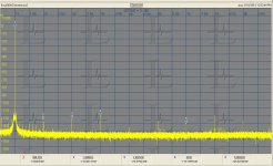
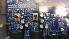
I was wrong about the EMU 0404 USB. It uses a different ADC, the AK5385. I'm attaching a photo of the pcb (I have higher res if someone needs) and the distortion spectrum.
Notes- over 1V and the input circuit distorts, pretty much regardless of the gain setting. Turning it up and reducing the input just raises the noise floor. This was 500K point and 7 averages at 96K sample rate. Its not stable enough to use at 192K. I may yet finds whatever is interfering and fix the sample rate.
Source is my ShibaSoku 590AR generator. Its residual is at least 6-10 dB better.
Its pretty good, not as good at the AK5394A demo board.
The other EMU's I have are not working as well on Windows. I may need to reinstall the drivers again.
Attachments
I sure would like to get the sample rate up higher than 192ksps. Will the available software do this though?
The DAC quality will degrade rapidly if you go above 192K. There is 384K and 768K stuff but the noise floor and distortion go up radically. What are you looking for up there? The QA100 scope may be your best tool for looking at higher frequencies. I use a Tek 7L5 to look for aliases on DACs, it works well.
The Atmel in the Audio Widget can't process the throughput to get above 192K. Its a limitation of the endpoints. We are looking at a TI that may well be able to but that's some time in the future.
You could also use undersampling and other arcane tricks to get extended response but probably not worth it.
I was wrong about the EMU 0404 USB. It uses a different ADC, the AK5385. I'm attaching a photo of the pcb (I have higher res if someone needs) and the distortion spectrum.
Notes- over 1V and the input circuit distorts, pretty much regardless of the gain setting. Turning it up and reducing the input just raises the noise floor. This was 500K point and 7 averages at 96K sample rate. Its not stable enough to use at 192K. I may yet finds whatever is interfering and fix the sample rate.
Source is my ShibaSoku 590AR generator. Its residual is at least 6-10 dB better.
Its pretty good, not as good at the AK5394A demo board.
The other EMU's I have are not working as well on Windows. I may need to reinstall the drivers again.
Hi Demian,
That's the same ADC as the 0204. I'll bet EMU uses the same input circuitry.
Are both channels balanced or is one unbalanced like the 0204?
The behavior was the same on the 0204 until I balance the differential signals into the ADC inputs. Scaling to 1Vrms by increasing the gain at the ADC input gives you an extra 6dB on ARTA or the like. The software must be recal'ed for the 1Vrms (0dB) to see this.
I guess the second picture answers the question.
Maybe I take a look at the balanced left channel on the 0204 and see what EMU has done.
For now input 1Vrms, increase the gain to just below clipping. Input -10dB to -20dB or what ever gives a clean result. Calculate the Vrms for that level and use that amount to cal the software. You should see a difference.
Cheers,
Last edited:
The DAC quality will degrade rapidly if you go above 192K. There is 384K and 768K stuff but the noise floor and distortion go up radically. What are you looking for up there? The QA100 scope may be your best tool for looking at higher frequencies. I use a Tek 7L5 to look for aliases on DACs, it works well.
The Atmel in the Audio Widget can't process the throughput to get above 192K. Its a limitation of the endpoints. We are looking at a TI that may well be able to but that's some time in the future.
You could also use undersampling and other arcane tricks to get extended response but probably not worth it.
There are 15 endpoints for USB fullspeed. How many end points are available with high speed and how many are being used? Why is the is the SDRwidget clocked with a 12MHz crystal? Is this for timing reasons?. I thought I read in the data sheet up to 20MHz.
When I ran USB throughput tests with a PICmicro if I decrease the clock from 20MHz to 19.45MHz I lost half the USB throughput. The USB modules are very sensitive to the clock speed used at least with the PICs. Using multiple EPs increases the throughput.
I think the limitation is with USB not with the particular micro used. The USB is a seperate module all the processor does is move data into a buffer.
Cheers,
- Status
- This old topic is closed. If you want to reopen this topic, contact a moderator using the "Report Post" button.
- Home
- Design & Build
- Equipment & Tools
- EMU0204 mods for FFT measurements