Sync:
Making progress. The difference in calibration is a distraction. I can explain its source later but for now ignore it. They are close enough. Now tune the 339 to 1 KHz and see what the level is. Tune up and down to find the lowest value.
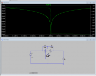
I just modded the twin tee to passive and it seems the 10K load (input of the QA400) is significant. The file is attached. You can download LTspice and run it, tweak the values to match the ones on your board and see what the effects are. Its almost impossible to get the simulated results. Real parts are not that perfect for more than a few seconds at a time.
Making progress. The difference in calibration is a distraction. I can explain its source later but for now ignore it. They are close enough. Now tune the 339 to 1 KHz and see what the level is. Tune up and down to find the lowest value.
I just modded the twin tee to passive and it seems the 10K load (input of the QA400) is significant. The file is attached. You can download LTspice and run it, tweak the values to match the ones on your board and see what the effects are. Its almost impossible to get the simulated results. Real parts are not that perfect for more than a few seconds at a time.
Attachments
@ David,
I'm using .01uF caps @ 600V. x 3.
Resistors 10k in series with 20K pot, for 22 KOhms, x 2.
A 10K pot for 5.6K ohms
T1: Connected to the center of two 22K ohms one .01uF 600V cap to ground.
T2: Connected to the center of two .01uF caps is one 5.6Kohms to ground.
I'm using .01uF caps @ 600V. x 3.
Resistors 10k in series with 20K pot, for 22 KOhms, x 2.
A 10K pot for 5.6K ohms
T1: Connected to the center of two 22K ohms one .01uF 600V cap to ground.
T2: Connected to the center of two .01uF caps is one 5.6Kohms to ground.
Synctronx you can do a frequency response test with the QA400.
Connect the QA400 left out to the input of your TT. Connect the output your TT to the left input of the QA400. Put the TT in bypass, if you installed a switch for this. Using gen1 set the frequency to 1KHz if that is what your TT is tuned for. Set the Gen1 level to 0dB. Click the FR button on the QA400. You should get something like this.
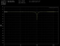
If the display is at -65dB or there about, hold the control key while left clicking on the dBV button. This will bring up a dialog pop up. Where it says input gain type in -65dB. Using the Ymax control adjust the scale to 10dB at the top so odB is visible.
Now with the ctrl key held down left click on Xlog button and set your frequency scale.
Never mind the Gen setup. You don't need it for FR.
Here is an example.
This shows the envelope of the TT.
Connect the QA400 left out to the input of your TT. Connect the output your TT to the left input of the QA400. Put the TT in bypass, if you installed a switch for this. Using gen1 set the frequency to 1KHz if that is what your TT is tuned for. Set the Gen1 level to 0dB. Click the FR button on the QA400. You should get something like this.
If the display is at -65dB or there about, hold the control key while left clicking on the dBV button. This will bring up a dialog pop up. Where it says input gain type in -65dB. Using the Ymax control adjust the scale to 10dB at the top so odB is visible.
Now with the ctrl key held down left click on Xlog button and set your frequency scale.
Never mind the Gen setup. You don't need it for FR.
Here is an example.
This shows the envelope of the TT.
Attachments
Last edited:
I've got that B&K 1607, that I can dial in.
It is apart but the measureing section is intact and I can
set the notch and tune it and see how different it is.
Ill just use banana jacks as I don't have two RCA
to BNCs.
That will tell me right off if t he difference in TT is
significant.
Or
I'll just plug the regular notch in and see what or how much
the losses are, after tuning it.
There is a problem with posting multiple pics here.
I'm not sure what is happening but posting multiple
pics, the DIY gallery seems to be mixing them up
somehow.
I can't be doing this poor of a job numbering them
and tyring to document for each iteration.
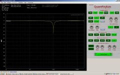
David, as the levels you recommended, w/o the notch
hooked up, when I press FR it ended up at 14 dB above
your screen setting.
So I adjusted the screen to show more just in case.
The FR is screwing up the notch, or the notch
is screwed up somehow. I measured each section
and they are set to 22Kohms.
It almost is acting like one of the capacitors is installed
backwards but that doesn't make sense. Somehow it is
inverting 1/2 the notch?
Let me flip the notch around and see what it does if anything.
I'm not sure what is happening but posting multiple
pics, the DIY gallery seems to be mixing them up
somehow.
I can't be doing this poor of a job numbering them
and tyring to document for each iteration.
David, as the levels you recommended, w/o the notch
hooked up, when I press FR it ended up at 14 dB above
your screen setting.
So I adjusted the screen to show more just in case.
The FR is screwing up the notch, or the notch
is screwed up somehow. I measured each section
and they are set to 22Kohms.
It almost is acting like one of the capacitors is installed
backwards but that doesn't make sense. Somehow it is
inverting 1/2 the notch?
Let me flip the notch around and see what it does if anything.
Demian,
The values of the TT that you derived, where did they come from?
They are different than the ones that I derived and found from
entering 1KHz.
I used this web site:
http://sim.okawa-denshi.jp/en/TwinTCRtool.php
I entered 1K into the Hz field which gave me the 22K ohm and .01uf caps.
The values of the TT that you derived, where did they come from?
They are different than the ones that I derived and found from
entering 1KHz.
I used this web site:
http://sim.okawa-denshi.jp/en/TwinTCRtool.php
I entered 1K into the Hz field which gave me the 22K ohm and .01uf caps.
Last edited:
There is a problem with posting multiple pics here.
I'm not sure what is happening but posting multiple
pics, the DIY gallery seems to be mixing them up
somehow.
I can't be doing this poor of a job numbering them
and tyring to document for each iteration.
David, as the levels you recommended, w/o the notch
hooked up, when I press FR it ended up at 14 dB above
your screen setting.
So I adjusted the screen to show more just in case.
The FR is screwing up the notch, or the notch
is screwed up somehow. I measured each section
and they are set to 22Kohms.
It almost is acting like one of the capacitors is installed
backwards but that doesn't make sense. Somehow it is
inverting 1/2 the notch?
Let me flip the notch around and see what it does if anything.
Then add 14 to the input value you have in there. If you used -65 then try -51. Do this until you have a 0dB reference or there about.
Posting pics, notch isn't correct.
Result:

Set up manually tuned notch for -40 dB:

Prep for test no notch:

Prep for more test:
First test set up:

Just use the FR function to set it up.
For some reason QA scaled down. The scale changes with number of point.
Not what I was expecting. You can fix it with the extra gain parameter so at least it reads correctly. It's all relative anyway.
I got the values from the same place. Set the resistor and the cap to E96. Then use the spice model to test and trim the values.
Your curve looks like the two networks are not matched for frequency or amplitude. Do you have a cap meter? If the caps are not pretty close you will have issues like you show.
Your curve looks like the two networks are not matched for frequency or amplitude. Do you have a cap meter? If the caps are not pretty close you will have issues like you show.
QA400 won't let you set up in FR mode.
Ok...
It won't let me set up in FR mode but it lets everyone else. : (
You have to stimulate QA400 to get it to repeat the test signal. All the test signals from the output of the QA400 are impulse type. The FR uses Impulse response for FR mode. If the QA400 sees a change then it repeats the output. So switch between TT and bypass to stimulate an output.
It makes tuning the notch next to impossible in this test.
ARTA for example uses PN pink, (Periotic Noise), or PN white as a stimulus which is a continuous signal. So tuning a notch is possible using ARTA. However as Bear pointed out unless the notch is tuned to the center of a bin you won't see the full notch.
So how do you get the generator in QA to stay on while you do the
FR measurement?
I guess we have to be careful what we say to folks.
It sounded like all I needed to do was slap a notch
together and it would work fine.
I guess if you aren't trying to do something finely
detailed it doesn't matter. At these levels it does
matter.
When you are trying for something fine, then
you just don't slap something together. We
need careful thinking of components, measuring
them, selecting the right voltage, thinking about
the cap construction other wise we get where
I am right now.
Demian, please tell me how we can be using the same value finder
for the TT notch. Even with teaking it.
My cap values are .01uF your cap values are 22.24nF?????
My resistor values are 22K - your resistor values are 7.15K????
or 8.5K on another resistor.
My ground caps is.01uF your ground cap is 44.48nF?????
The only thing that looks remotely similar is the layout.
I"ll get there eventually.
Confusion IS a learning strategy.
Last edited:
You can use the HP as the signal source (open circuit is should be at least 3V) and it can be tuned easily. For tuning a notch looping through with the HP as source and level meter should be the quickest way to dial the notch in. The HP input impedance is 100K, source is 600 Ohms so it should all work. Then use the QA400 as an FFT analyzer. Turn off the generator and just monitor its output, as you have been doing.
Hang in there and you will start understand all of this. My technician is struggling with this stuff as well. Its not easy or obvious at first.
Hang in there and you will start understand all of this. My technician is struggling with this stuff as well. Its not easy or obvious at first.
So how do you get the generator in QA to stay on while you do the
FR measurement?
I guess we have to be careful what we say to folks.
It sounded like all I needed to do was slap a notch
together and it would work fine.
I guess if you aren't trying to do something finely
detailed it doesn't matter. At these levels it does
matter.
When you are trying for something fine, then
you just don't slap something together. We
need careful thinking of components, measuring
them, selecting the right voltage, thinking about
the cap construction other wise we get where
I am right now.
The Panasonic polypropylene work wonders for me. When I tested them for matching on an ESI bridge I got an exact null per pair of three sets. Not bad.
You can't get a continuous signal from the QA400 output.
- Home
- Design & Build
- Equipment & Tools
- QuantAsylum QA400 and QA401