Hi all,
I am working on a function generator circuit which will do sine, square and triangle waves at audio frequencies to be used for testing amplifier circuits and similar. I don't need to get to .0000000000000000002% or anything like that as this is just a hobby project but I would like to get it as clean as possible, of course. Perhaps 0.01% distortion would be a good target. Additionally, I don't have a distortion analyzer, just an old analog scope, so I have to rely on coming up with a good circuit design without actually being able to measure the result.
This is my core oscillator circuit:
http://en.wikipedia.org/wiki/File:We...Oscillator.png
though, on my breadboard, I currently have this one wired up:
http://www.4qdtec.com/sinz/invwein.gif
(discussion is here: 4QD-TEC: Audio signal (sinewave) generators)
I want to run this off a single supply of either 9 or 12 volts and that's why I'm using the 4qdtec circuit currently. The plan is to use the standard circuit (as in the wikipedia link) but use another op amp to provide a 1.5V voltage reference by, basically, detaching R1 and C1's left connections from the wikipedia diagram and connecting them to the 1.5V reference.
The only other twist that makes my circuit different than the standard one is that I would like to use the resistor side of optocouplers in place of R1 and R2 (see 1st diagram link). I'll be using Silonex NSL-32H-101 parts since I just bought 100 of them on the cheap. The goal in this is that I'm wanting to use a microcontroller with an output PWM voltage to control the frequency of the circuit... but this is just for overview, not really part of my question except for the fact that A) optocoupler LDRs do add their own distortion compared to actual resistors and B) the resistors will be mismatched fairly poorly compared to precision resistor values.
I've been studying up on the Wien Bridge circuit math and there are a few questions I haven't been able to find an answer to.
A) if I mismatch the two legs of the wien bridge circuit (the series RC versus the parallel RC) does that add distortion? Or does it just change the oscillation frequency? Simulating it, I only see that the frequency changes if I randomly change the 4 R and C values, but I don't see any misshaping of the waveform.
B) Where does the amplitude or midpoint voltage come from in the standard circuit (see link 1)? I know the frequency is 1/(2 Pi R C) if R and C are matched but I don't know what determines the final amplitude. When I experiment with a variable resistor in place of the two R's I see the amplitude seems to change (randomly?) at some frequencies but there's no overall decrease or increase across the frequency spectrum that I can see.
C) Why do most circuits use multiple switched values for their capacitors, one per decade or what have you? With a value of, say, C=100nF and R=82 to 10082 I've gotten a frequency span of about 200 Hz to 20K Hz and the circuit oscillates throughout and the amplitude is similar. Is it just because it's too hard to adjust a knob to that level or is there a distortion factor? My goal is to use a feedback loop with the microcontroller so it would be doing the minute frequency adjustments, checking the resulting frequency then readjusting until the desired frequency is obtained. Is there anything wrong with using a single C value along with an R value swing of this magnitude?
D) This is extra credit (lol) but in the 4QD circuit (link 2), I had wired up the original circuit with ceramic, cheap caps and it handled the frequency range of 200Hz-20kHz without ceasing to oscillate at any point in the range and without any obvious clipping; then I bought a bunch of polyester film caps and used those; then, suddenly, adjusting the 500R resistor (see link 2) became a very, very sensitive chore where the high frequencies would stop oscillating unless I reduced the 500R knob a bit but then, when I'd lower the frequency back to 200Hz, it would be clipped a bit (over-amplified). The end result was that I couldn't really tweak the circuit to handle the full frequency range with the polyester caps, but could with the ceramic caps. Please ignore this one unless I'm missing something obvious")
E) Is using PWM to control the two R's of a Wien Bridge a bad idea? It would run at maybe 40kHz or 100kHz, run through a low pass filter for smoothing then finally control the two opto couplers which represent the two resistors of the Wien Bridge. (This one can be extra credit too )
If anyone has any input into any of these questions, it would be greatly appreciated! I've been mulling over this project for like two months now and really need to just build something. A sanity check on any of these thoughts would be most helpful!
I am working on a function generator circuit which will do sine, square and triangle waves at audio frequencies to be used for testing amplifier circuits and similar. I don't need to get to .0000000000000000002% or anything like that as this is just a hobby project but I would like to get it as clean as possible, of course. Perhaps 0.01% distortion would be a good target. Additionally, I don't have a distortion analyzer, just an old analog scope, so I have to rely on coming up with a good circuit design without actually being able to measure the result.
This is my core oscillator circuit:
http://en.wikipedia.org/wiki/File:We...Oscillator.png
though, on my breadboard, I currently have this one wired up:
http://www.4qdtec.com/sinz/invwein.gif
(discussion is here: 4QD-TEC: Audio signal (sinewave) generators)
I want to run this off a single supply of either 9 or 12 volts and that's why I'm using the 4qdtec circuit currently. The plan is to use the standard circuit (as in the wikipedia link) but use another op amp to provide a 1.5V voltage reference by, basically, detaching R1 and C1's left connections from the wikipedia diagram and connecting them to the 1.5V reference.
The only other twist that makes my circuit different than the standard one is that I would like to use the resistor side of optocouplers in place of R1 and R2 (see 1st diagram link). I'll be using Silonex NSL-32H-101 parts since I just bought 100 of them on the cheap. The goal in this is that I'm wanting to use a microcontroller with an output PWM voltage to control the frequency of the circuit... but this is just for overview, not really part of my question except for the fact that A) optocoupler LDRs do add their own distortion compared to actual resistors and B) the resistors will be mismatched fairly poorly compared to precision resistor values.
I've been studying up on the Wien Bridge circuit math and there are a few questions I haven't been able to find an answer to.
A) if I mismatch the two legs of the wien bridge circuit (the series RC versus the parallel RC) does that add distortion? Or does it just change the oscillation frequency? Simulating it, I only see that the frequency changes if I randomly change the 4 R and C values, but I don't see any misshaping of the waveform.
B) Where does the amplitude or midpoint voltage come from in the standard circuit (see link 1)? I know the frequency is 1/(2 Pi R C) if R and C are matched but I don't know what determines the final amplitude. When I experiment with a variable resistor in place of the two R's I see the amplitude seems to change (randomly?) at some frequencies but there's no overall decrease or increase across the frequency spectrum that I can see.
C) Why do most circuits use multiple switched values for their capacitors, one per decade or what have you? With a value of, say, C=100nF and R=82 to 10082 I've gotten a frequency span of about 200 Hz to 20K Hz and the circuit oscillates throughout and the amplitude is similar. Is it just because it's too hard to adjust a knob to that level or is there a distortion factor? My goal is to use a feedback loop with the microcontroller so it would be doing the minute frequency adjustments, checking the resulting frequency then readjusting until the desired frequency is obtained. Is there anything wrong with using a single C value along with an R value swing of this magnitude?
D) This is extra credit (lol) but in the 4QD circuit (link 2), I had wired up the original circuit with ceramic, cheap caps and it handled the frequency range of 200Hz-20kHz without ceasing to oscillate at any point in the range and without any obvious clipping; then I bought a bunch of polyester film caps and used those; then, suddenly, adjusting the 500R resistor (see link 2) became a very, very sensitive chore where the high frequencies would stop oscillating unless I reduced the 500R knob a bit but then, when I'd lower the frequency back to 200Hz, it would be clipped a bit (over-amplified). The end result was that I couldn't really tweak the circuit to handle the full frequency range with the polyester caps, but could with the ceramic caps. Please ignore this one unless I'm missing something obvious
E) Is using PWM to control the two R's of a Wien Bridge a bad idea? It would run at maybe 40kHz or 100kHz, run through a low pass filter for smoothing then finally control the two opto couplers which represent the two resistors of the Wien Bridge. (This one can be extra credit too
)If anyone has any input into any of these questions, it would be greatly appreciated! I've been mulling over this project for like two months now and really need to just build something. A sanity check on any of these thoughts would be most helpful!
Your first link is incomplete, so it goes nowhere.
As to your questions:
A) Mismatching changes both the frequency and the attenuation of the Wien bridge circuit, which means that the level control (the 6V lamp in the 4QD circuit) has insufficient range of level control given a wide range of mismatch.
B) In a perfectly matched Wien bridge, the AC output from the bridge will be exactly 1/3 of the AC input to the bridge. Mismatching changes this attenuation factor which has consequences for the level control circuitry, and that is what keeps level constant and distortion low.
C) Most circuits use a narrower range of adjustment in order to control the size of the loads from both the level control and the Wien bridge on the output of the oscillator amplifier. A 50 ohm total load will be hard for many circuits to drive, so the caps are switched to keep the resistor values in a reasonable range -- typically from several kilohms to tens of kilohms.
D) Cheap ceramic caps are piezoelectric generators, so it is possible that they are contributing some voltage that keeps everything working -- or more realistically, maybe their tolerance spread and resulting mismatch as frequency varies is such as to offset the level effects of the resistive mismatches. Don't really know. The Poly caps are likely to have a much lower spread of values -- ie, tighter tolerance, which may make the effects fo the existing resistor mismatch worse.
E) PWM is OK but be prepared for some distortion; but given your level of test gear, you won't likely be able to see it. I can visually see about 1-2% THD on a scope, but I've had lots of practice.
As to your general desire for having multiple waveforms, you can use a squaring circuit (Google Schmitt trigger) to transform the sine wave into a square wave, and then another circuit (integrator) to convert the square waves into triangle waves.
Function generators start with a square wave generator, then convert to triangle, and then use a special series of resistors and diodes on the triangle wave to generate more-or-less sine-shaped waves. They generally have THD well above 0.1% -- typically 0.5 to 1%.
Thanks for the insightful answers! That's an enormous help and lots to ponder on. And I was planning on doing the sine to square to triangle wave path, though the triangle wave is a bit wonky at his point. I have purchased some op amps with a higher slew rate which I'm hoping will help.
I can't seem to edit my first post so I'll repost the missing link:
Wein Bridge Oscillator - Wikipedia, the free encyclopedia
Thanks again!
Patrick
I can't seem to edit my first post so I'll repost the missing link:
Wein Bridge Oscillator - Wikipedia, the free encyclopedia
Thanks again!
Patrick
My guess of a possible answer to question D) is that the cheap capacitors were ceramic and the capacitance changed with voltage which helped control the feedback. The large value multilayer type can have a large reduction in capacitance with voltage.
I have found Oscillators difficult to stabilize because the amplitude change with time is an exponential of the Oscillation frequency x gain error.
I have found Oscillators difficult to stabilize because the amplitude change with time is an exponential of the Oscillation frequency x gain error.
Hi Patrick -- the Wikipedia file shows the simplest form of a Wien bridge oscillator, and this form can be found in a Linear Technology App Note on oscillators and bridges, although I can't at the moment remember the number.
The reactive legs of the bridge (assuming equal Cs and equal Rs) results in an AC attenuation of 3, while the resistor + lamp leg has to have approximately the same attenuation -- this means for a lamp, which is not intended to run at full operating voltage, but rather at around 10% of rated voltage, that has an operating resistnace in circuit of say 150 ohms, the resistor will have to be 2x that value or 300 ohms.
If you're using an opamp like the LM49710 or LT1037, then I suggest using the 1869 type lamp, available from Mouser. The reactive feedback path blocks the DC from the output, while the resistive feedback path sets the DC output level of the amp. If you want the oscillator output to be zero volts DC, then use an opamp with split power supplies. To use the single-ended version and get maximum output swing, return the bulb to a low impedance voltage divider at half the positive supply which is bypassed at the bulb by a large electrolytic cap for low AC impedance to ground.
Use a pot in series with the feedback resistor to adjust for lowest THD and best stability.
See my webpage on lamps for oscillators -- www.moorepage/Lamps.html
I have found Oscillators difficult to stabilize because the amplitude change with time is an exponential of the Oscillation frequency x gain error.
Thank you for your input. I definitely concur! I am trying to calibrate the oscillator to handle a range of about 200Hz to 20 kHz and it's not easy task. Probably a strong argument for using multiple switched capacitors, however...
If you're using an opamp like the LM49710 or LT1037, then I suggest using the 1869 type lamp, available from Mouser. The reactive feedback path blocks the DC from the output, while the resistive feedback path sets the DC output level of the amp. If you want the oscillator output to be zero volts DC, then use an opamp with split power supplies.
I am using a Radio Shack lamp rated at 5V, 25mA. I can see the "bounce," it's definitely doing something, so I'm not sure if it's part of the problem. I also have a 12V version which I haven't tried yet. My supply is currently 12V, single-ended.
I have rewired the circuit using the op-amp version instead of the 4QD version. My first observation is... it doesn't really work!
I think I failed to consider the amount of current the op amp has to drive due to the lamp. My first try was with a LM833 and that does oscillate and the wave looks very clean, but it's only oscillating at about 2V p-p; that wouldn't really be a big problem except that I feel I'm overloading it. I also tried an NE5532 and a TLC2272; neither of those oscillated at all with the lamp. If I removed the lamp and put in place a 10K resistor and a pot for the feedback resistor it oscillated just fine. That makes me think it's a current issue.So I don't know at the moment if I'll buy some higher current op amps, perhaps those Dick suggested, or if I'll go back to the 4QD circuit. Just thinking out loud here (so to speak) but I guess two other avenues would be using one of my life-time-supply of Silonex optocouplers in place of the lamp or some hybrid solution with some kind of transistor buffer between the output and the resistive leg of the feedback loop. Don't know if the latter's possible but I seem to remember seeing something like that.
As far as the single supply goes, I'm mimicking the circuit in figure 15-10 in this link:
http://www.ti.com/lit/an/slod006b/slod006b.pdf
I'm using a second op amp to generate a 2V reference voltage in place of "Vref." This is supposed to bring my output's midpoint to 6V.
To use the single-ended version and get maximum output swing, return the bulb to a low impedance voltage divider at half the positive supply which is bypassed at the bulb by a large electrolytic cap for low AC impedance to ground.
I like this idea better because it's based on half the supply, but I can't get it to simulate correctly. I attached the circuit I _think_ you were describing but I may have gotten something wrong
Thanks for all the input guys!
Attachments
Thanks for posting the circuit; that looks great! I'm kind of set on using the lamp, but this might work well too.
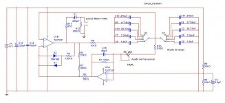
I attached my current circuit for the oscillator core. I added a transistor buffer past the op amp and it's helping a whole lot with the calibration. It's a lot more stable within a pretty large frequency range. It doesn't do well past about 12k so I'm thinking that has to do with current delivery from the voltage reference op amp as the resistors get small -- I've seen some voltage sag.
I'm really hoping to get this working without switching any caps, though, as I want to control the frequency with optocouplers driven by a microcontroller (see attached). I'm going to set up an AGC the same way, too, but that will be _after_ the selected waveform (square, sine or triangle) is switched into the next stage of the circuit.
Attachments
a google search produced this nice read and circuit...
http://www.janascard.cz/PDF/An ultra low distortion oscillator with THD below -140 dB.pdf
/paba
http://www.janascard.cz/PDF/An ultra low distortion oscillator with THD below -140 dB.pdf
/paba
You read my mind. I was just thinking about that! I have tweaked and calibrated my circuit to where I am now getting my full target range of 100Hz-20kHz without cap-switching. This is using two optocouplers in the wien bridge sharing a current source and attached to a pot. But the last couple days I've been thinking about how I might go about swapping the lamp out for a third optocoupler. Especially, I'm thinking if I could reduce the output level to a smaller value, that would be better for overall distortion caused by the optocouplers; then re-amplify with an op amp. With a lamp, it has some pretty fixed properties and you have to work around that but optocouplers seem much more controllable as far as how sensitive you want them to be, what kind of time constant you want them to have, etc., since one piece is completely isolated from the other. I've only found one other similar circuit to this so this is a great find that I will definitely check out further.
I have tweaked and calibrated my circuit to where I am now getting my full target range of 100Hz-20kHz without cap-switching. This is using two optocouplers in the wien bridge sharing a current source and attached to a pot. But the last couple days I've been thinking about how I might go about swapping the lamp out for a third optocoupler. Especially, I'm thinking if I could reduce the output level to a smaller value, that would be better for overall distortion caused by the optocouplers; then re-amplify with an op amp. With a lamp, it has some pretty fixed properties and you have to work around that but optocouplers seem much more controllable as far as how sensitive you want them to be, what kind of time constant you want them to have, etc., since one piece is completely isolated from the other. I've only found one other similar circuit to this so this is a great find that I will definitely check out further.You know you can buy an IC that does all you want - a complete function generator. More than one mfr but here's one: XR2206. And a complete kit of it is available if you just want to get down to business and use the instrument.... but you wont learn as much...
Go to www.Electronics-diy.com
Such as this simple circuit ready made on pcb:

It wouldnt be too hard to design a ss variable R that would allow you to sweep the oscillator (maybe auto switching C as well). AND, a tracking BPF to reduce thd to very low number? Sorry.... getting carried away.
Thx-RNMarsh
Go to www.Electronics-diy.com
Such as this simple circuit ready made on pcb:
It wouldnt be too hard to design a ss variable R that would allow you to sweep the oscillator (maybe auto switching C as well). AND, a tracking BPF to reduce thd to very low number? Sorry.... getting carried away.
Thx-RNMarsh
Last edited:
Thanks! Yes, I actually have an XR2206 chip, but I am enjoying this project as more of a design challenge/learning experience. It's actually functional now and meets my original specs but then I started thinking about optocouplers. A "tracking BPF," huh? I googled it and it looks like something I will not be able to figure out
For distortion of an FM tuner, i would think .1% or less THD is needed.
-RNM
I respectively disagree except for tube tuners of course and some really poor performing solid state ones.
Thanks
/paba
Poor tube or ss tuners? Like the Marantz 10B (0.5%) or the ss Magnum DynaLabs at 0.1%
If you are well under 0.1% in any tuner you are exceptional. I always try to be at least 10 times under the thd of what I measure so as to trust the test numbers I get. For tuners, that would put it at .01%..... your stated target.
You can also buy used commercial units off eBay for a couple hundred bucks with .002% or less. Just some more ideas for you. Plus some web sites that have schematics for low distortion oscillators and mfr maintenance manuals with oscillator schematics. For <$40 you can get a SOTA oscillator from Viktor on eBay at .00005%. Already made.
Thx-RNMarsh
Last edited:
FWIW, the XR2206 is a nice but obsolete chip. The ones easily available today seem to have some problem meeting their voltage specs. Over about 11 VDC they won't cover their range, if they oscillate at all. Under that they seem to work OK.
Though I don't know the distortion that can be achieved, the Analog Devices DDS chips seem to be the way to go these days in terms of function generators.
For a nice low THD analog circuit, I like the generator Bob Cordell uses in his THD analyzer. It's a state variable circuit using common opamps that performs very well.
Poor tube or ss tuners? Like the Marantz 10B (0.5%) or the ss Magnum DynaLabs at 0.1%
Thx-RNMarsh
I just checked 3 low cost tuners from my collection for kicks and specs are
@1K, 100% mod:
Sony ST-S555 ES (0.08%), 1985
Sony ST-J60 (0.08%), 1978
Kenwood KT-900 (0.04%), 1981
Most japanese tuners from this period will have distortions specs in this range. Say up to the late 80's.
I always try to be at least 10 times under the thd of what I measure so as to trust the test numbers I get. For tuners, that would put it at .01%..
Thx-RNMarsh
fully agree on this. That's why the XR2206 won't cut it with .1% spec.
But an FM stereo gen with 0.01% out of the RF output is really best in class and meguro and other instruments that can do that are pricey. I think finding an affordable stereo gen that does 0.05% is more realistic and would cover a great deal of tuners. the 80%-20% rule I guess.
cheers
paba
If the spec were from Tek or HP etc I would believe them. Competitive products for consumers... and relatively cheap ones, I dont believe until they are measured.
Back then, what instrument/test equipment did they use to measure those numbers with?
Not saying they are not well below .1% but asking. I might trade-in my MagnumDyna Lab.
Thx-RNMarsh
Back then, what instrument/test equipment did they use to measure those numbers with?
Not saying they are not well below .1% but asking. I might trade-in my MagnumDyna Lab.
Thx-RNMarsh
Last edited:
Like I said a few posts back, some tuner manufacturers had suspicious specs but if we read the 1978 Yamaha T-2 owner's manual they say they used the following instruments to measure their tuner.
VHF SG: Meguro MSG-297 or 296
VHF SG: GE501
stereo moduluator: Meguro MSG-211 (one of the best ever btw)
Distortion analyzer HP4333A
All very credible.
and finally the
The T-2 spec is 0.05%
hope that clarifies
paba
VHF SG: Meguro MSG-297 or 296
VHF SG: GE501
stereo moduluator: Meguro MSG-211 (one of the best ever btw)
Distortion analyzer HP4333A
All very credible.
and finally the
The T-2 spec is 0.05%
hope that clarifies
paba
- Status
- This old topic is closed. If you want to reopen this topic, contact a moderator using the "Report Post" button.
- Home
- Design & Build
- Equipment & Tools
- Wien bridge oscillator math