Hi,
I made some more measurements, with various Cx caps.
My prev. measurements were incorrect.
Nat. freq. of trany approx. 169.503 kHz
1. Ceramic 0.01uF, resonant freq.= 155.038 kHz
L Leakage = 0.0172 mH
2. Not sure of type, 0.018uF, resonant freq.= 134.344 kHz
L Leakage = 0.029 mH
3. MKP 0.033uF, resonant freq.= 105.500 kHz
L Leakage = 0.0422 mH
The leakage values seem to vary a bit. The bigger the capacitor the larger the calc. leakage. Should i keep increasing the value till the leakage result converges hopefully?
Regards,
Chris
It sounds like your results are diverging rather than converging. I think it may be prudent to simply give up on this type of measurement and try something else.
You could try to find someone near you who owns an LCR meter, and ask them to measure the secondary inductance twice; once with primary open and again with primary shorted. Perhaps you could find such a person by posting a message here on the diyaudio site.
Or you could use the approximate rule of thumb that transformer leakage inductance is very roughly 5% of total inductance (secondary inductance with primary open-circuited). Measure secondary inductance, either with an LCR meter or with a sinewave generator and a resistor, then multiply by 5%. By the way, since the L is ~ 20X greater, the resonant frequency will be about sqrt(20) = 4.5X lower. Perhaps the sinewave generator measurement approach will work better for you around 38 kHz than it did around 170 kHz.
If the sinewave generator approach does work well for you with the primary open circuited, i.e., if measurements with 3 different external capacitors all give the same extracted Ltotal, then you can also extract an approximate value of secondary interwinding capacitance from these measurements. Because secondary interwinding capacitance doesn't change much when you short the primary vs. open circuit the primary.
I'd like to call your attention to pages 8-11 of the Hagerman paper. Here he discusses using a capacitor (with no resistor) as a "snubber". This doesn't eliminate oscillatory ringing, but it does lower the resonant frequency. Next he talks about using this parallel capacitor AND a conventional RC snubber. The parallel capacitor lowers the resonant frequency, and the RC snubber kills the ringing. This 3 component snubbing network has the great advantage that it frees you from measuring the secondary interwinding capacitance. Just make the parallel capacitor much much larger than any possible secondary capacitance, and voila, Ctotal = Cparallel.
The 13 VA transformer that Hagerman measured, had a secondary capacitance of 550 picofarads. The 80 VA transformer that I measured, had a secondary capacitance of 1300 picofarads. I'm pretty confident that yout transformer's secondary capacitance is within a factor of 3, either way, from that. So if you installed a 150,000 pF (0.15 uF) capacator in parallel with your RC snubber, you would now be absolutely certain that the LC resonant circuit has C = 0.15 uF exactly. And the resonant frequency would fall by about sqrt(150000 / 1300) = 11X.
Finally, keeping in mind that your end goal is to design a snubber, you could decide to build yourself a little test board that lets you directly observe snubber performance and lets you easily change the snubber resistance. Something along the lines of Bob Cordell's book Fig 16.10; it's designed to let you easily monitor the rectifier voltage (including all of the oscillatory ringing due to poor snubbing) without the headache of common mode voltage. This will let you empirically select the snubber resistance that gives a damping "zeta" which pleases you. It'll probably take 2 hours to design the board, 2 hours to build it, and 1 hour to run the experiments with different values of snubber resistance. And now you've got a jig that lets you do the same measurements again, some day in the future, when you want to fiddle with a different transformer.
Yes,I typically use about 5 or 6 values in a wide range from 47 pf to 680pf and then find the approximate value that is common to all combinations of the values I used.
A fellow DIYer plots them on a chart and finds the crossing point on a chart as shown here,
http://www.diyaudio.com/forums/plan...p-up-measurements-part-1-2-a.html#post2823887.
If your transformer has any electrostatic shields this will complicate matters even more.
I am working with two transformers right now in a step-up configuration.
One that I have had laying around as in my earlier tests here,
http://www.diyaudio.com/forums/planars-exotics/161485-step-up-transformer-design-2.html#post2101604
And an Antek AS-1206 that has shielding in its construction.
Both transformers exhibit quadrupling of the leakage inductance as they should when the HV winding's (now secondary) are connected in series as the leakage inductance is proportional to to the square of the number of turns.
Another words if the turns are doubled the leakage inductance quadruples.
As described here,
OTimpedance
Now for the confusion.
My core shows also the doubling of the stray capacitance when the secondary are connected in series.
This should cut the impedance seen by the driving amp in half and is confirmed by the doubling of the of the primary current using just the transformer self capacitance as a load at 10Khz and 20Khz
The Antek on the other hand shows the same actions for the leakage inductance as expected.
But the capacitance on the other hand and is halved ifor the series connection of the secondary winding.
In both situations I was using the same resonate mode of measurement with a 1 ohm resistor feeding the primary's.
But upon measuring the primary current for both transformers clearly shows the doubling of the primary current for the series connection of the secondary.
Keep in mind that this is a doubling of the transformation ratio as well.
Completely opposite results between the two transformers with the very same setup using this technique.
Except for the results of measuring the primary current is exactly the same for both in the same situations.
Now since then during a core saturation test I had burned a few winding's on the Antek AS-1206 and I had stripped it down to the to the 115v winding and removed the electrostatic and outside magnetic shields.
Fixed and repaired the burn't and shorted winding and rewound a new primary with the same number of turns that was on it.
And now I still get the very same opposite results compared to my other transformer with whatever shields that I could remove, removed!
I have stripped off the extra winding's on my first core and this lowered my capacitance a good deal.
But I haven't gotten down to the 115V winding's yet in order to see if they are maybe wound very differently causing these very strange measurements.
Sorry,I am not trying to go off topic or hijack your thread.
I am just expressing my recent discovery's using this method and now I am thoroughly confused of which is the correct way and what measures that I may not be accounting for, As my application is different than yours.
FWIW
jer")
A fellow DIYer plots them on a chart and finds the crossing point on a chart as shown here,
http://www.diyaudio.com/forums/plan...p-up-measurements-part-1-2-a.html#post2823887.
If your transformer has any electrostatic shields this will complicate matters even more.
I am working with two transformers right now in a step-up configuration.
One that I have had laying around as in my earlier tests here,
http://www.diyaudio.com/forums/planars-exotics/161485-step-up-transformer-design-2.html#post2101604
And an Antek AS-1206 that has shielding in its construction.
Both transformers exhibit quadrupling of the leakage inductance as they should when the HV winding's (now secondary) are connected in series as the leakage inductance is proportional to to the square of the number of turns.
Another words if the turns are doubled the leakage inductance quadruples.
As described here,
OTimpedance
Now for the confusion.
My core shows also the doubling of the stray capacitance when the secondary are connected in series.
This should cut the impedance seen by the driving amp in half and is confirmed by the doubling of the of the primary current using just the transformer self capacitance as a load at 10Khz and 20Khz
The Antek on the other hand shows the same actions for the leakage inductance as expected.
But the capacitance on the other hand and is halved ifor the series connection of the secondary winding.
In both situations I was using the same resonate mode of measurement with a 1 ohm resistor feeding the primary's.
But upon measuring the primary current for both transformers clearly shows the doubling of the primary current for the series connection of the secondary.
Keep in mind that this is a doubling of the transformation ratio as well.
Completely opposite results between the two transformers with the very same setup using this technique.
Except for the results of measuring the primary current is exactly the same for both in the same situations.
Now since then during a core saturation test I had burned a few winding's on the Antek AS-1206 and I had stripped it down to the to the 115v winding and removed the electrostatic and outside magnetic shields.
Fixed and repaired the burn't and shorted winding and rewound a new primary with the same number of turns that was on it.
And now I still get the very same opposite results compared to my other transformer with whatever shields that I could remove, removed!
I have stripped off the extra winding's on my first core and this lowered my capacitance a good deal.
But I haven't gotten down to the 115V winding's yet in order to see if they are maybe wound very differently causing these very strange measurements.
Sorry,I am not trying to go off topic or hijack your thread.
I am just expressing my recent discovery's using this method and now I am thoroughly confused of which is the correct way and what measures that I may not be accounting for, As my application is different than yours.
FWIW
jer
Last edited:
Thank you transistormarkj for your detailed analysis, I really appreciate it! So the basic message is, well actually there's a few here but the first one is:Measure the secondaries inductance with primary-opened instead of the leakage, cause its 20x larger and approx. the leakage by taking 5% of it. Yes, I will try it with my 3 capacitors and post the results later. Thanx for the tip! As far as the snubber network is concerned, I was planning on using 1 parallel capacitor and 1 in series with a resistor, e.g. a la Hagerman. For me, I could prob. assume that my leakage lies in the middle of Haggerman's value and yours, e.g. 925pF. Your assumption of 3x 550, e.g. ~ 1500pF is a bit more. Is bigger better or just safer when one cannot measure it exactly?What about the capacitance of the diodes in a fullwave rectifier? Haberman, mentions it and approximates 50 pF according to the datasheet. For two in series he says its half, so wouldn't that be than 25pf? Also I looked up a std. 1N4007, I found it to be 15pF, which != Haberman's 50pf?? Mayabe I shouldn't be so picky about these little values but I would like to understand it....I may start off with 0.1uF values, since I have a few. Maybe they may fit with my L measurments above, let's c. I Plan to measure the ringing later when the power supply is built. Any tips on measureing this, e.g. hook the scope up to the output of the bridge?It shouldn't be that hard to change a few caps and resistors if its still bad. My main objective here is more of an educational one. I just wanted to understand how snubbers work on a learning by doing, instead of copying blindly the schematics of others.Also thanx for the tip about Bob Cordell, he seems to quite a knowledgable guy! I will def. check his book out.Best regards,Chris
Last edited:
Hi sorry about the prev. post. my browser didn't allow me to edit it correctly!
Here's a more readable version:
Thank you transistormarkj for your detailed analysis, I really appreciate it!
So the basic message is, well actually there's a few here but the first one is:
Measure the secondaries inductance with primary-opened instead of the leakage, cause its 20x larger and approx. the leakage by taking 5% of it.
Yes, I will try it with my 3 capacitors and post the results later. Thanx for the tip!
As far as the snubber network is concerned, I was planning on using 1 parallel capacitor and 1 in series with a resistor, e.g. a la Hagerman. For me, I could prob. assume that my leakage lies in the middle of Haggerman's value and yours, e.g. 925pF. Your assumption of 3x 550, e.g. ~ 1500pF is a bit more. Is bigger better or just safer when one cannot measure it exactly?
What about the capacitance of the diodes in a fullwave rectifier? Haberman, mentions it and approximates 50 pF according to the datasheet. For two in series he says its half, so wouldn't that be than 25pf?
Also I looked up a std. 1N4007, I found it to be 15pF, which doesn't equal Haberman's 50pf??
Maybe I shouldn't be so picky about these little values but I would like to understand it.
I may start off with 0.1uF values, since I have a few. Maybe they will fit with my L measurments above, let's c.
I Plan to measure the ringing later when the power supply is built. Any tips on measureing this, e.g. hook the scope up to the output of the bridge?
It shouldn't be that hard to change a few caps and resistors if its required.
My main objective here is more of an educational one. I just wanted to understand how snubbers work on a learning by doing example, instead of copying blindly the schematics of others.
Also thanx for the tip about Bob Cordell, he seems to quite a knowledgable guy! I will def. check his book out.
Best regards,
Chris
Hi,
ok i made some induction measurements on the secondary with various capacitors.
assumptions:
-primary opened
-used prev. resonance freq. equations to det. it
1. without any Cx or extra capacitor:
resonant freq.: 9.2031 kHz
2. with Cx=0.01uF:
resonant freq.: 5.326 kHz, calc. inductance: 0.06 mH
3. with Cx=0.018:
resonant freq.: 4.0453 kHz, calc. inductance: 0.07 mH
4. with Cx=0.033:
resonant freq.: 3.0247 kHz, calc. inductance: 0.07 mH
The values look a lot better now.
Not sure of the units, are they mH's or H's?
Guess if all is ok, I should go with the 0.07 value. An approx. value for the leakage could be 5% of that value or: 0.0035.
Cheers,
Chris
Its a good idea to find the inductance using a capacitor signal generator and a scope.
I have 2 LC meters and neither were every accurate. One meter told me the inductor was 100uH when it was really 10uH ! The other was a bit closer with 60uH when it should be 10uH. This really screwed up the calculations for my half bridge switch mode power supply. Due to the 10uH my power supply just went into over current mode and locked out.
I have 2 LC meters and neither were every accurate. One meter told me the inductor was 100uH when it was really 10uH ! The other was a bit closer with 60uH when it should be 10uH. This really screwed up the calculations for my half bridge switch mode power supply. Due to the 10uH my power supply just went into over current mode and locked out.
Hello everyone,
since my measurements seemed to be so random and I was quite unsure of myself or my methods, i wrote a letter to Talema to ask them if they would make some measurements for me.
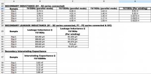
See the attached file, its an excel sheet in open office format
Transformer is a Talema:
model: RKPT 25218, 25 VA
primaries: 2x 115v can be wired in series for 230v
secondaries: 2x 18v
Equipment used for the measurements:
Waynekerr 3260B
NOTE: the secondary measurements were made with the windings connected together in series, so one must divide those values by 4 to get a per winding value. I've done that for some of them, e.g. Sec. + Sec. Leakage Inductance. See also (Per Winding) caption.
My induction measurements of 0.07mH@3 kHz were "way" off compared to his. He measured 0.41H@1kHz or 410mH!?
Maybe for such transformers with 2x Primareis + 2x Secondaries, both Secondaries must be tied together in order to get correct measurements?
I will remeasure with both secondaries connected to see if my results are more comparable to his!
Cheers,
Chris
since my measurements seemed to be so random and I was quite unsure of myself or my methods, i wrote a letter to Talema to ask them if they would make some measurements for me.
See the attached file, its an excel sheet in open office format
Transformer is a Talema:
model: RKPT 25218, 25 VA
primaries: 2x 115v can be wired in series for 230v
secondaries: 2x 18v
Equipment used for the measurements:
Waynekerr 3260B
NOTE: the secondary measurements were made with the windings connected together in series, so one must divide those values by 4 to get a per winding value. I've done that for some of them, e.g. Sec. + Sec. Leakage Inductance. See also (Per Winding) caption.
My induction measurements of 0.07mH@3 kHz were "way" off compared to his. He measured 0.41H@1kHz or 410mH!?
Maybe for such transformers with 2x Primareis + 2x Secondaries, both Secondaries must be tied together in order to get correct measurements?
I will remeasure with both secondaries connected to see if my results are more comparable to his!
Cheers,
Chris
Hi again,
just made a measurement of the secondary inductance using the following methods/values:
-Cx value of 0.033uF
-both secondaries connected in series
-signal generator voltage of 1v
-signal generator freq.@ resonance: 1268 Hz
-primaries opened
Calc. result of: 0.477405938 H
Seems to agree quite nicely with his corresponding meas. of 0.42H per winding! However that value was det. from his by dividing his parallel measurements by 4.
What i did differently:
-connecting both secondaries in series
-setting the sig. generators voltage to about 1v
What is a little strange is that his measurements were for both secondaries, e.g. why didn't i calc. 4x 0.47 or 1.9096!?
Instead i got directly the value per winding??
So the mystery continues.....
Cheers,
Chris
Can anyone familiar with Hagerman's snubber Paper verify the logic of my calculations here?
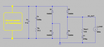
I'm a little confused about how to calculate the snubber capacitor Cs and the snubber resistor Rs, when using the "extra" Cx cap.
1. Rs = sqrt(Lt / Ceq),
where Lt = sec. leakage inductance. For my transformer, I'm using 74.01 uH
2. Ceq = Ct + Cd + Cx,
where Ct = sec. interwinding capacitance, Cd diode capacitance and Cx, snubber capacitor.
3. Cs = 2 * pie * sqrt(Lt * Ceq) / Rs
According to Hagerman, if Cx is much much larger than Ct + Cd, Ceq = Cx. For my Cx value of 0.1uF this should hold, since Cd is approx. 50 pF and Ct for my transformer is about 3578 pF
If i put in my values, i get this:
Rs = 27.20 ohms
Cs = 0.628 uF
Cx = 0.1 uF
So i would use Cx across the supply rails followed by Rs + Cs in series across the supply rails.
Thanx,
Chris
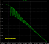
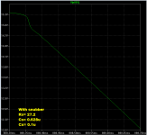
You could verify it yourself using LTSPICE. You could simulate the transformer + rectifier + filter + load, twice: once without the snubber, and again with the snubber. Then you could eyeball the waveforms and ask yourself, does this look OK?
Of course, simulations can fall victim to the garbage-in, garbage-out syndrome. If the circuit you simulate is incorrect, the simulation result will be incorrect too. In this case, if the transformer measurements were incorrect, or if you have interpreted the measurements incorrectly, or if you incorrectly translate them into a circuit model for simulation, then you've got garbage-in. You will naturally receive garbage-out.
I've attached a simulation schematic which shows one way you can test your snubber in LTSPICE. I deliberately left out the hard part -- interpreting the measurements and forming a simulation model -- so as not to rob you of the opportunity to learn by doing, and to learn more by doing-over. Fill in the yellow box and simulate. You may get results that match mine, which are also attached.
However, keep several points in mind: (1) the measured data might be WRONG. (2) your interpretation of the measured data might be WRONG. my interpretation might be wrong too. (3) when you convert the measured data into an LTSPICE simulation model, you might do that WRONG. so might I.
If any link in the chain is WRONG, from measurements, to interpretation of measurements, to circuit modeling; then you've given garbage-in to LTSPICE. You should expect garbage-out.
Also, don't neglect the possibility that I and others on this website may be agents of Satan, placed on earth to mislead you with falsehoods, half-truths, irrelevancies, and non sequitirs. Don't blindly trust everything you see on websites.
Attachments
Thanx again transistormarkj.
Do I really sound that gullible?
I'm just a novice whose interested in deepening his electronics knowledge.
For all i know, you could be some evil sales man wanting to sell me stuff i don't need like the wrong capacitors for my snubber network....
Looking at Hagerman's equivalent circuit, i would fill in your little yellow box with.
-an inductor with my leakage value
-a cap in series with it using my interwinding cap.
I will def. try that out.
Btw. your results with my snubber values look quite ok, assuming you modeled/ interp. everything correctly.
Chris
I would like to measure the ringing across my power supply diodes using the test setup proposed in Bob Cordell's Audio Amplifiers Book. For the test setup circuit, see the attached schematic.
Could anyone familiar with that method, explain to me what is meant by that earth connection, which i have circled.
If i were to connect it to GND, this would be directly shorting the positive rail and would end up cooking my diode(s).
Is this earth simply the earth on the pwr chord?
Thanx,
Chris
Could anyone familiar with that method, explain to me what is meant by that earth connection, which i have circled.
If i were to connect it to GND, this would be directly shorting the positive rail and would end up cooking my diode(s).
Is this earth simply the earth on the pwr chord?
Thanx,
Chris
Attachments
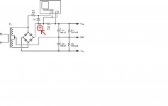
To measure the voltage across a component using a 'scope, it can be very convenient to ground one end of the component.
A PSU is normally grounded at the output end of the 0V rail. Provided the whole circuit is otherwise floating then, apart from stray capacitance issues, it can be grounded anywhere. Remember, the 0V rail is only 0V because someone decided to ground it. Apart from that, there is nothing 0V about it; it is merely Vrail above the 'negative' rail and Vrail below the 'positive' rail. Voltage always is a comparison between two points.
A PSU is normally grounded at the output end of the 0V rail. Provided the whole circuit is otherwise floating then, apart from stray capacitance issues, it can be grounded anywhere. Remember, the 0V rail is only 0V because someone decided to ground it. Apart from that, there is nothing 0V about it; it is merely Vrail above the 'negative' rail and Vrail below the 'positive' rail. Voltage always is a comparison between two points.
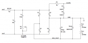
This little test jig is adapted from Bob Cordell's Figure 16.10 on page 353. It lets me observe oscillatory ringing of the power transformer's secondary, and to observe the damping effects of the snubbing network (Rs, Cs, Cx) as I adjust Rs. I like to dial Rs until I get a damping factor (zeta) of approximately 0.8. Then I simply turn off the power, remove the (socketed) trimpot from the jig, and measure Rs on my ohmmeter. Snubber design for this transformer is now complete! Without performing a single inductance or capacitance measurement.
The snubber's parallel capacitor Cx swamps out the capacitance of the transformer secondary, plus the junction capacitance of any rectifier I could possibly select, so the transformer + snubber work together well in the final application, even with different layout and lead lengths. Even with different rectifiers.
I like to use extremely "slow" (long tRR) diodes in the jig; they seem to give the largest amplitude of oscillatory ringing and the longest duration of ringing.
Sharp eyed readers may note that I've modified the output network (R1, D5, D6) a little bit, compared to Bob Cordell's original. I'm using two low capacitance signal diodes instead of one high capacitance rectifier. I've also cut the resistance by 10X, to be less sensitive to fixture and probe capacitance. The good news is, you can simulate all of this in LTSPICE and customize the output network however YOU like.
To avoid overheating the 30 ohm, 50 watt load resistor, keep the transformer secondary voltage below { sqrt(30*50)/sqrt(2) } = 27.4 volts RMS. If your secondary voltage is higher, either feed the primary from a variac, or change to a different load resistor arrangement. Also be mindful of the filter capacitor voltage rating.
I chose this particular load value so I could measure an Antek AS3218, which is a 300VA toroid with two 18 volt secondaries. It runs the secondary at about 0.8 amps, plenty enough to get the diodes switching on and off hard, so they'll sing their RF tune.
In case anyone wondered, "Dprot" is supposed to protect the surprisingly expensive, high ripple-current, low ESR filter capacitor from reverse bias, in case I accidentally install one or more of the bridge diodes backwards. I'd rather blow the fuse than explode a large electrolytic capacitor.
Attachments
- Status
- This old topic is closed. If you want to reopen this topic, contact a moderator using the "Report Post" button.
- Home
- Design & Build
- Equipment & Tools
- Leakage Inductance