looks ok. for 20 bucks u cant beat it
Transistor Tester Capacitor ESR Inductance Resistor Meter NPN PNP Mosfet/9V | eBay
Transistor Tester Capacitor ESR Inductance Resistor Meter NPN PNP Mosfet/9V | eBay
I would like to tell you, that the china transistor tester with ESR and inductance measurement is copied from the german internet side AVR Transistortester - Mikrocontroller.net .
At the end of this side you find a download area for software and PDF documentation.
The project has been started by Markus F. and I had added some new features.
It is free software, anyone can use it.
You will find in the documentation (also in english language) information about measurement principle and results.
I hope, that my english was good enough to explain all.
Regards
Karl-Heinz Kübbeler
Sinzig, Germany
ah just found it! http://www.mikrocontroller.net/attachment/143988/TTester_096k.pdf
Thank you for the wonderful work on this - if there is a donation page someplace for this, let me know.
Mods - suggest we move this thread to the Equipment & Tools section .. cheers
Thank you for the wonderful work on this - if there is a donation page someplace for this, let me know.
Mods - suggest we move this thread to the Equipment & Tools section .. cheers
I will send the new documentation because the access of the svn archive is something difficult.
The 096k release is a early software version without ESR and inductance measurement.
I have added some hints for the access of svn data in english language now.
Regards,
Karl-Heinz
The 096k release is a early software version without ESR and inductance measurement.
I have added some hints for the access of svn data in english language now.
Regards,
Karl-Heinz
Attachments
Karl, Thanks this is useful.
Is there someone selling the original/official version of this board also so we can have a chance to adapt some of the software a little. EG, the mosfet threshold voltage measurement will be very helpful if we can get 2 decimals, etc etc.
This way also allows us to give some recognition to the folks who put in the hard work for this wonderful little device.
Anyway, thanks again!
Hi kasey197,
there is no official version of the board. Different board versions are implemented by some users. Most of them for the first release from Markus Frejek. The software can be also adapted to the first board revision.
The major changes of the new circuit are, that the measurement resistors should be measurement type with 0.1% error only. The capacitor at the
AREF Pin should be reduced from 100nF to 1nF and a 8 MHz crystal should be added with two 22pF capacitors for generating the clock.
With this changes and software optimizing the measurement quality of capacity and resistance could be enhanced.
Because of the better measurement quality the influence of VCC voltage has a noticeable effect to the measurement results of capacity measurement.
So a 2.5V precision voltage reference has been connected to a free ADC input to monitor the VCC voltage.
There is a full featured strip line board design in the Hardware section of the SVN archive (SVN == subversion).
If you are interested in the threshold voltage of MOS Transistors, you should know, that the measurement is time critical. If the gate capacity is very low, the 470 kOhm resistor charges the gate too fast, so that the gate is overloaded after the drain switches and the software switches off the load current. A additional capacity connected to the gate and source will help you to get a better result.
Best Regards,
Karl-Heinz

...Mods - suggest we move this thread to the Equipment & Tools section .. cheers
We may be slow, but we get there in the end. Thread moved.
")
Results of analysing the china version
I had got one of the first series. The board is called "Booster edition Ver 2.1 2012/11/06", Transistor-L/C ESR Tester.
The board with the LCD display was delivered without any documentation!
The label of the ATmega is not readable. But I had added the 10 pin ISP connector to the board. I had added a additional GND connection to pin 10 of the ISP connector too. So I could check, that there is a ATmega168 or ATmega168A installed on my board.
I am not sure if the installed 8 MHz crystal has been used by setting the right fuses of the ATmega.
The original software was my version 1.02k . I have flashed my version 1.04k and set the fuses to crystal operation.
On my board a 2.5V zener diode was connected to pin PC4 of the ATmega. I had measured a voltage of only 2.2V. I have replaced this zener diode by a LT1004 precision voltage reference (2.5V) as originally designed.
Next I have done a self test by connecting all three pins together. Integrated with the self test is a automatic calibration.
You need a external capacitor with a capacity of 100nF - 20uF connected to pin 1 and pin 3 to finish the calibration.
At test step 4 you must disconnect the pins.
The capacitor must be connected with the display message
"1-||-3 >100nF" in row one.
After all this work I have noticed, that a direct connection of two pins together results to a resistor message with a result of 0.3 Ohm.
I have checked with my LCR meter, that one signal path from test pin to the pin of the SMD ATmega has a resistance of 0.15 Ohm.
This resistance is much more than the one of all prototype boards
and is not compensated by the software.
This will be the reason of the different ESR measurement results of this board version.
I don't know, if some of the bugs are eliminated with the newer Chinese board version.
Best regards,
Karl-Heinz
CapAnalyzer 88A series II checks electrolytic capacitors
I just purchased The [FONT=Helvetica, Sans, Arial][SIZE=-1]CapAnalyzer 88A series II [/SIZE][/FONT] checks electrolytic capacitors in-circuit for both ESR and DCR with no unsoldering. It is the only capacitor tester that discharges the cap, checks it for low DC Resistance (DCR) up to 500 ohms, reads out high-frequency Equivalent Series Resistance (ESR) from 0.1 ohm to 20 ohms, and compares your readings to industry standards on the three-color chart right on the front panel. The included one-handed tweezer probe with beryllium copper tips allows testing of both normal and surface-mounted electrolytics and uses coaxial cable instead of normal test-probe wire for stable readings on small capacitors.
I love this tester and it is super in circuit tester. I was very impressed.
purchased it from EDS. I saw it advertised in NutsNVolts magazine (published in UK) sold in US book stores.
Electronic Design Specialists Products: CapAnalyzer 88A | LeakSeeker 82B
Nice d
I just received the device, it arrived quickly. Search Ebay for ESR tester. For the price of 20 Euro I really can't complain, but there are issues.
There is no manual, and the seller send only excuses, like it's easy to use anyway, and it's Chinese New Year now. So I don't expect much from him.
I understand from others here, this is a copied design, of which the makers have allowed the software to be copied.
My questions:
1) Who has a manual?
2) I believe there is a calibration routine, but I don't want to damage the software by wrong use of this. If I change the Zener Diode for a precision 2.5V reference, I suppose I need new calibration.
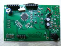
3) On the right side of the PCB is room for a USB connector. (Picture attached) If I put that in, can I upgrade the software? Or what things can I do then? I suppose that is standard Arduino hardware, because Chinese only copy things as always.
4) There is battery charge circuit there, but no compoments mounted. Does it make sense to do so? Will it charge from the USB port?
5) Resistance measurement is reasonably accurate in most ranges. Just not above 2k. Starting exactly above 2k it makes an error of appr 200 Ohms. Which error gets
less imporant at higher values, and at 500k or so, 200 Ohms gets invisible, so it measures correct again. in the2k range would like to fix this. Is there a solution for this?
6) What is the reason they removed the printing from processor? There is something they not want us to know. Mmm.. so what is that...?
7) Last one... Is it possible to attach a larger size display to it, with backlighting?
All in all it's an AMAZING device, there is really a lot of intelligence in the software, every time I play with it, the things amazes me. So I hope to get something more out of it with a better calibration, and having the manual.
I tested a speaker chassis with it, you can hear what it does, and get nicely the results in Ohms + Henry.
What is really great is to attach a random transistor to it, any way you like, and the device tells you: FET or PNP or NPN and the connections. With FET one working pint, and with Bipolar the hfe (current gain). Absolutely amazing. No more searching in databooks for any unknown devices. Imagine the convenience! You suspect some randon transistor is broken. (Like from a power supply). Without databook, this device tells you "good or bad". Well of course it's only a hint about good or bad, but
I seldom had a "half bad" transistor, they were allways still ok, or totally dead. So this device really does a fantastic job here.
I am a bit reluctant to test in-ciruit capacitors with it. Perhaps anyone knows what voltage the device can withstand in case some charge is left?
So this device has a lot of weaknesses, and you never know what the makers have been doing. They may not even know themself. Only copy something. Still for 20 Euro I wouldn't want to miss it any more.
Sorry for all of the questions, but if someone knows the anwers to some of the questions, that would be great!
-Jac
I just received the device, it arrived quickly. Search Ebay for ESR tester. For the price of 20 Euro I really can't complain, but there are issues.
There is no manual, and the seller send only excuses, like it's easy to use anyway, and it's Chinese New Year now. So I don't expect much from him.
I understand from others here, this is a copied design, of which the makers have allowed the software to be copied.
My questions:
1) Who has a manual?
2) I believe there is a calibration routine, but I don't want to damage the software by wrong use of this. If I change the Zener Diode for a precision 2.5V reference, I suppose I need new calibration.
3) On the right side of the PCB is room for a USB connector. (Picture attached) If I put that in, can I upgrade the software? Or what things can I do then? I suppose that is standard Arduino hardware, because Chinese only copy things as always.
4) There is battery charge circuit there, but no compoments mounted. Does it make sense to do so? Will it charge from the USB port?
5) Resistance measurement is reasonably accurate in most ranges. Just not above 2k. Starting exactly above 2k it makes an error of appr 200 Ohms. Which error gets
less imporant at higher values, and at 500k or so, 200 Ohms gets invisible, so it measures correct again. in the2k range would like to fix this. Is there a solution for this?
6) What is the reason they removed the printing from processor? There is something they not want us to know. Mmm.. so what is that...?
7) Last one... Is it possible to attach a larger size display to it, with backlighting?
All in all it's an AMAZING device, there is really a lot of intelligence in the software, every time I play with it, the things amazes me. So I hope to get something more out of it with a better calibration, and having the manual.
I tested a speaker chassis with it, you can hear what it does, and get nicely the results in Ohms + Henry.
What is really great is to attach a random transistor to it, any way you like, and the device tells you: FET or PNP or NPN and the connections. With FET one working pint, and with Bipolar the hfe (current gain). Absolutely amazing. No more searching in databooks for any unknown devices. Imagine the convenience! You suspect some randon transistor is broken. (Like from a power supply). Without databook, this device tells you "good or bad". Well of course it's only a hint about good or bad, but
I seldom had a "half bad" transistor, they were allways still ok, or totally dead. So this device really does a fantastic job here.
I am a bit reluctant to test in-ciruit capacitors with it. Perhaps anyone knows what voltage the device can withstand in case some charge is left?
So this device has a lot of weaknesses, and you never know what the makers have been doing. They may not even know themself. Only copy something. Still for 20 Euro I wouldn't want to miss it any more.
Sorry for all of the questions, but if someone knows the anwers to some of the questions, that would be great!
-Jac
Attachments
I just ordered one too as it looked quite interesting and then found this thread.
I really want to get a Peak atlas ESR tester but cant afford it right now and we have 2 where I work I can use when I really need to.
I'm also really interested to know more about the units and get some documentation, and learn about any other things that can be done with it.
Is this the same unit?
http://www.mikrocontroller.net/articles/AVR-Transistortester
(view via google translate or in chrome browser for translated version)
Last edited:
- Status
- This old topic is closed. If you want to reopen this topic, contact a moderator using the "Report Post" button.
- Home
- Design & Build
- Equipment & Tools
- another ebay gadget