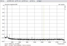
The THD plots...it goes to show where the next improvements should be concentrated, now that I learned my way inside  . More on this later.
Well, happy soldering for now! If someone manages to duplicate these results it will be reassuring. Just let us know!
. More on this later.Well, happy soldering for now! If someone manages to duplicate these results it will be reassuring. Just let us know!
Attachments
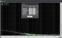
I forgot to post the results for dynamic range. Still some little gremlins bellow -132dB or so...at these levels it gets complicated, we need to consider shielding , I think.
There is also a 12k component that appeared on the right channel, or I'm seeing it only now because everything is cleaned around. (see it in the previous posts with SNR and THD too).
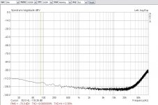
On the downside my mod degrades the crosstalk, it is now down 3-4dB at 20k (~ -84 dB absolute), because the new wiring hovers above the right channel over a length of 3/4 inch or so...I don't really mind.
But I had to inform you...
, I think.There is also a 12k component that appeared on the right channel, or I'm seeing it only now because everything is cleaned around. (see it in the previous posts with SNR and THD too).
On the downside my mod degrades the crosstalk, it is now down 3-4dB at 20k (~ -84 dB absolute), because the new wiring hovers above the right channel over a length of 3/4 inch or so...I don't really mind.
But I had to inform you...
Attachments
The THD plots...it goes to show where the next improvements should be concentrated, now that I learned my way inside
Well, happy soldering for now! If someone manages to duplicate these results it will be reassuring. Just let us know!
E-MU 0404 is workhorse interface for me. I've always considered bang for the buck performance out of the box as superb. For acoustically derived signals the left channel interference never concerned me; however is limitation in using interface for assessing performance of other circuits.
Your analysis, and proof by modification appears excellent, and will make nice science when duplicated.
I've certainly enough experience to perform modifications as detailed here.
Before going under knife and iron a few questions:
What are values of R151 and R167? And removing their resistances doesn't impact performance, why?
How do you come up with degradation in crosstalk?
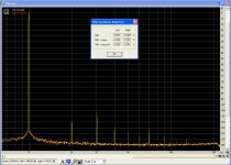
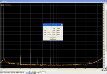
In OEM condition with -1dBFS 1kHz input on right channel, loop antenna of left input picks up:
(click to enlarge)

and with signal left, right is tight:

So here at 1kHz right channel picks up about 15dB less signal from right channel, than left channel picks up from right channel. Is this good assessment?
If in your mod, black wire additionally connected from R110 twisted onto wire up to R108, would this form shield/balance common mode signal for possible improvement?
Hi,
R151, R167 are zero ohm jumpers. There are also two of these for the right channel (R143, R147). They include these locations as a precaution in case there was ringing on the anti-glitch capacitor or to make an attenuation pad + 1st order LPF (when combined together with the resistive part of the ADC's input impedance). Apparently they decided that there was no need for these which served my purpose well
It is also a hint that they did not spent too much time in development, making a second run of the layout after the prototyping phase.
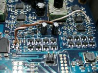
About the wires: I twisted them to ensure mechanical stability and minimal loop area. It looks like the black wire is coiled around the yellow, that is because the yellow is stiffer. About the segment of yellow wire that runs alone...keep it short and running close to the board - there shouldn't be any problems there.
About the whole crosstalk issue, let me run a test first, my external cables are kinda creepy...(pieces joined togheter)
What are values of R151 and R167? And removing their resistances doesn't impact performance, why?
.................
If in your mod, black wire additionally connected from R110 twisted onto wire up to R108, would this form shield/balance common mode signal for possible improvement?
R151, R167 are zero ohm jumpers. There are also two of these for the right channel (R143, R147). They include these locations as a precaution in case there was ringing on the anti-glitch capacitor or to make an attenuation pad + 1st order LPF (when combined together with the resistive part of the ADC's input impedance). Apparently they decided that there was no need for these which served my purpose well
It is also a hint that they did not spent too much time in development, making a second run of the layout after the prototyping phase.
About the wires: I twisted them to ensure mechanical stability and minimal loop area. It looks like the black wire is coiled around the yellow, that is because the yellow is stiffer. About the segment of yellow wire that runs alone...keep it short and running close to the board - there shouldn't be any problems there.
About the whole crosstalk issue, let me run a test first, my external cables are kinda creepy...(pieces joined togheter)
Last edited:
As I remember:
The chassis separates in two; do this first. You can pull out the knobs later. Careful with the ground lift switches as you slide the two parts.
You don't need to pull out the knob for Direct Monitor level. The other 4 are a ...ch! Lift them slowly with a small screwdriver.
The chassis separates in two; do this first. You can pull out the knobs later. Careful with the ground lift switches as you slide the two parts.
You don't need to pull out the knob for Direct Monitor level. The other 4 are a ...ch! Lift them slowly with a small screwdriver.

The left channel working very well. Many thanks to sidiy.
THD 0.00092%, THD+N ... 0.0015% (HeadPhone loopback, 24bit/48KHz sampling).
Ikoflexer for us (Greek) the 7.7 is a major earthquake with a lot of damage and lost in human beings, except if the center of earthquake done in the sea (with deep level).
You are afraid for tsunami, if I understood well!
THD 0.00092%, THD+N ... 0.0015% (HeadPhone loopback, 24bit/48KHz sampling).
Ikoflexer for us (Greek) the 7.7 is a major earthquake with a lot of damage and lost in human beings, except if the center of earthquake done in the sea (with deep level).
You are afraid for tsunami, if I understood well!
Attachments
Good news all over, I'm glad it worked.
Earthquake? I hear all is well, our friends in BC may have some stories for us.
I'll try next some improvements on CMRR, decoupling and I may even change some of the op-amps and 'lytics. But I'll need to raise a schematic and order some parts...don't wait for me.
Earthquake? I hear all is well, our friends in BC may have some stories for us.
I'll try next some improvements on CMRR, decoupling and I may even change some of the op-amps and 'lytics. But I'll need to raise a schematic and order some parts...don't wait for me.
Mod results:
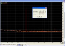
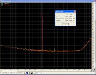
Open loop:

This is clear improvement over stock condition.
Left input referenced to -1dBFS with 1kHz sine by adjusting output, left output used:

Right input with cable moved from left input, same signal:

From above results, left channel remains susceptible to signal.
Excellent mod! Thanks for the adventure.
I hope your talents are fruitful and otherwise well employed.
Regards,
Andrew
Open loop:
This is clear improvement over stock condition.
Left input referenced to -1dBFS with 1kHz sine by adjusting output, left output used:
Right input with cable moved from left input, same signal:
From above results, left channel remains susceptible to signal.
Excellent mod! Thanks for the adventure.
I hope your talents are fruitful and otherwise well employed.
Regards,
Andrew
What should I like as next mod for this emu?
1) Better input noise, over 30KHz
2) Multiturn output pot with better precision between the two channels.
3) Multiturn input pots (many times I have struggled too much to get a certain level (dBV) entry.
Item 3 I have struggled with also.
Agreed on number 3.
Currently we seem to have a "Pot2" for input and a "Pot9" for Headphones and Output level. The tapper for Pot2 seems to be custom made for EMU (they don't list a 02C, only a 05C).
Link: 11mm Rotary Potentiometers
Having the footprint and pinout we should try first to find something equivalent in multiturn,...but I'm not too optimistic. Other solutions imply some sort of mechanical hack...
sidiy, like Alpha inputs pots I find the Bourns PTV Serie (20K, 20%, 50mW) but it is not a multiturn, it has the same Resistance Tolerance characteristics : ± 20%. None improvement from Alpha!
Another solution for pecisely input pots, but not dimensional equivalent, is the Vishay Spectrol Series (2W, 20K), 10 no of turns, linear, same axle diameter (6mm), with better Resistance Tolerance characteristics : ±5%, Linearity tolerance ±0.25%.
It would supported to the upper pcb with nut and connected with the under pcb by wires, but has only 3 pins not 4 like emu's.
Equivalent to Vishay Spectrol is the ETI Systems MW22B-20K (MW22B-10-20K ETI Systems | Mouser)

Another solution for pecisely input pots, but not dimensional equivalent, is the Vishay Spectrol Series (2W, 20K), 10 no of turns, linear, same axle diameter (6mm), with better Resistance Tolerance characteristics : ±5%, Linearity tolerance ±0.25%.
It would supported to the upper pcb with nut and connected with the under pcb by wires, but has only 3 pins not 4 like emu's.
An externally hosted image should be here but it was not working when we last tested it.
Equivalent to Vishay Spectrol is the ETI Systems MW22B-20K (MW22B-10-20K ETI Systems | Mouser)
I forgot to post the results for dynamic range. Still some little gremlins bellow -132dB or so...at these levels it gets complicated, we need to consider shielding
There is also a 12k component that appeared on the right channel, or I'm seeing it only now because everything is cleaned around. (see it in the previous posts with SNR and THD too).
On the downside my mod degrades the crosstalk, it is now down 3-4dB at 20k (~ -84 dB absolute), because the new wiring hovers above the right channel over a length of 3/4 inch or so...I don't really mind.
But I had to inform you...
Sorry for digging this thread out, nut I like to find out if this mod will change the input impedance?
thanks
- Home
- Design & Build
- Equipment & Tools
- E-MU 0404 USB 2.0 and some "artifacts peaks" on left channel