Capacitor ESR varies a lot with temperature, so that could be a reason for measurement differences if you haven't controlled that aspect.
I don't know of a full schematic, so you likely have to reverse engineer sections of the schematic around parts you have an interest in.
I don't know of a full schematic, so you likely have to reverse engineer sections of the schematic around parts you have an interest in.
The improvement appeared to remain when retested the next day so I don't think it was warm up. I was assuming more that it was an effect resulting from no bias on the electrolytics for many years. They are about 15 years old and I suspect this unit had not been powered up for quite a few years.
If no one knows the usage of C51 I will try probing from C51 to the AK4396 pins in order to figure out the purpose and then select an appropriate replacement capacitor type and value.
On another site someone suggested an OPA2132 upgrade. I have some OPA2134 that I could try. (They seem to work well for the filter after the CS4398 so perhaps they will work well in a similar function for the AK4396.)
Attachments
Good soundcards don't die, they just get modified!
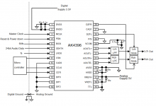
Just checking who has modified their 0404 to just use an unbalanced only input function that sidiy identifies in his "Left_in_mod.jpg" schematic from post #64? The mods cover:
I also use my 0404 just for unbalanced inputs, so am contemplating doing the same mods, along with the mod to disable the -6dB soft limit (removing R121, R122, R123), but I have no need to pursue IC or pot swaps, or what appears to be a reduced input impedance from 1Meg to 150k.
Sidiy hasn't been active on the forum for awhile, so just canvasing any experiences, especially the removal of the 47uF coupling caps C12-C17 as that would pass input dc through to U9 inputs. For me that would almost eliminate LF phase shift and gain droop due to the RC corner that sits around 5-10Hz (depending on sampling rate) - which should be a bonus for some of my testing.
Also I reckon the 48V dc/dc may be easiest to disable by removing U10 and L5 parts, as I can't easily identify a 5V feed to the boost circuitry that could be cut.
Just checking who has modified their 0404 to just use an unbalanced only input function that sidiy identifies in his "Left_in_mod.jpg" schematic from post #64? The mods cover:
- relocation of the overvoltage protection diodes D13-D14 to inputs of U1 (were on inputs of U9).
- removal of SW1 contacts from signal path, along with C12-C17 47uF 63V coupling caps.
- removal of 48V phantom power from input circuitry by removing R44, C26.
- disabling the 48V dc/dc converter (not shown in schematic or described in detail, but possibly by removing U10 and L5 parts).
I also use my 0404 just for unbalanced inputs, so am contemplating doing the same mods, along with the mod to disable the -6dB soft limit (removing R121, R122, R123), but I have no need to pursue IC or pot swaps, or what appears to be a reduced input impedance from 1Meg to 150k.
Sidiy hasn't been active on the forum for awhile, so just canvasing any experiences, especially the removal of the 47uF coupling caps C12-C17 as that would pass input dc through to U9 inputs. For me that would almost eliminate LF phase shift and gain droop due to the RC corner that sits around 5-10Hz (depending on sampling rate) - which should be a bonus for some of my testing.
Also I reckon the 48V dc/dc may be easiest to disable by removing U10 and L5 parts, as I can't easily identify a 5V feed to the boost circuitry that could be cut.
Hi,
Not active, but I still remember my logon") .
.
I disabled the phantom power 'by the book' - lifting pin4 of U10 and tying it to the gnd side of C41 next to it. In retrospect I think I googled the marking on U10 'PHOI' + sot23-5 and stumbled on TPS6104 datasheet... then took a chance .
The XLR part of the input connector is/was strictly a microphone input with low input impedance, it required those big non-pol 47uF and then the relay for source switching only adds grief, so I completely bypassed those. The TRS part of the input connector is still a balanced input, using a 'mono' TS jack transforms it in a single ended input, no other mods are necessary other than using decent adapters. I reduced the input impedance to 150k since the input OpAmp is bipolar and the entire stage is DC coupled, so a bit more sensitive to offsets...etc. An AP has max 100k input impedance so I thought we should be good. And finally for test and measurement purposes the use of a '-6dB soft limiter' is also unnecessary as it adds stuff of its own, so it had to go out.
Thinking out loud about other mods... Bill Withlock's common mode servo is not very useful now since the input buffers offer equal output impedance and a short signal path. The mod consists in removing R89, R90, C40, then replacing R57 with a 0ohm and tying pin3 of U15 to gnd - this will not affect performance at all. On the contrary it may reduce a bit the distortion introduced by the whole instrumentation amp (U9A, U9B and surrounding parts). I have not done it on mine, but if anyone wants to try it... The same operation must be performed on the right channel of course...
Not active, but I still remember my logon
.I disabled the phantom power 'by the book' - lifting pin4 of U10 and tying it to the gnd side of C41 next to it. In retrospect I think I googled the marking on U10 'PHOI' + sot23-5 and stumbled on TPS6104 datasheet... then took a chance
.The XLR part of the input connector is/was strictly a microphone input with low input impedance, it required those big non-pol 47uF and then the relay for source switching only adds grief, so I completely bypassed those. The TRS part of the input connector is still a balanced input, using a 'mono' TS jack transforms it in a single ended input, no other mods are necessary other than using decent adapters. I reduced the input impedance to 150k since the input OpAmp is bipolar and the entire stage is DC coupled, so a bit more sensitive to offsets...etc. An AP has max 100k input impedance so I thought we should be good. And finally for test and measurement purposes the use of a '-6dB soft limiter' is also unnecessary as it adds stuff of its own, so it had to go out.
Thinking out loud about other mods... Bill Withlock's common mode servo is not very useful now since the input buffers offer equal output impedance and a short signal path. The mod consists in removing R89, R90, C40, then replacing R57 with a 0ohm and tying pin3 of U15 to gnd - this will not affect performance at all. On the contrary it may reduce a bit the distortion introduced by the whole instrumentation amp (U9A, U9B and surrounding parts). I have not done it on mine, but if anyone wants to try it... The same operation must be performed on the right channel of course...
This is where I discover that AK5385 is obsolete...
For a real DC coupled system you can try also disabling the ADC's HPF (pin 19). According to the datasheet it is -3dB down at 1/2/4Hz depending on sample rates and drops fast below as this is a digital filter. As with any DC coupled system ... utmost care with max input levels, latch-ups, static...
For a real DC coupled system you can try also disabling the ADC's HPF (pin 19). According to the datasheet it is -3dB down at 1/2/4Hz depending on sample rates and drops fast below as this is a digital filter. As with any DC coupled system ... utmost care with max input levels, latch-ups, static...
Last edited:
Sidiy, thanks for commenting - much appreciated.
I have some doubt about how U10 functions in this circuit, as it does not directly drive the main FET Q15 afaik, and pin 4 (enable) is controlled by unknown logic (but obviously related to the front panel 48V On switch). Certainly the pin 3 feedback circuitry is nominal for a TPS6104, but I'm not sure how Q15 is controlled. Grounding the enable pin should stop any switching, although afaik ~4V would still be present on the 48V feed. The simple option appears to be to just remove R44, C26, R59, C27, and to ensure the front panel 48V switch is off.
I sometimes have wonky 1/4" jack issues, so am going to link the ring to sleeve, and remove the SW relay coil control from socket circuitry to alleviate any Neutrik socket related issues. The input relays can then be left de-energised, and to reduce 5V power by 280mW (~9%).
Given a fixed unbalanced input, I only need to rewire the nearby D4 protection diode CT to U1/3 for input protection to rails. I will retain the 1Meg input impedance, as that is a benefit for my application, and see how one modified channel compares to the other as an interim measure.
I had measured the input LF -3dB at 5Hz for 192k rate (4Hz ADC), and 2.8Hz for 44k rate (1Hz ADC), so removing the 47uF coupling cap will help somewhat, although replacing the 47uF with 220uF was my other simple option to maximise LF response.
Anyone is still using this card? Till Windows 10 was using it only to measure speakers. But with 11 it refused to work. Lately I needed to make some electrical measurements so I had to either buy something new or resurrect E-MU.\
My type was Motu M4 but while I looked ad it it's not significantly better than E-MU (for noise level, for thd it is) so I decided to make resurection.
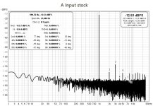
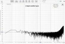
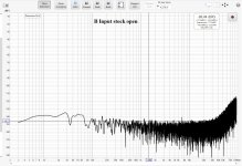
I installed Windows 8.1 (although for balanced input I had to change Windows recording gain from +30 to 0) and as it seemd to work fine with it I decided to do left channel mod.
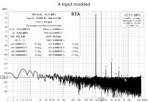
More or less it went fine, higher artifacts are gone. Only second harmonics seems to be much higher then for right channel. Wondering if it's worth to change those fixing wire for left channel to shielded. Probably it will not change anything. What do you think about it?


My type was Motu M4 but while I looked ad it it's not significantly better than E-MU (for noise level, for thd it is) so I decided to make resurection.
I installed Windows 8.1 (although for balanced input I had to change Windows recording gain from +30 to 0) and as it seemd to work fine with it I decided to do left channel mod.
More or less it went fine, higher artifacts are gone. Only second harmonics seems to be much higher then for right channel. Wondering if it's worth to change those fixing wire for left channel to shielded. Probably it will not change anything. What do you think about it?
Last edited:
My modified EMU404 has the same issue, left is worse in THD.But anyway even on other people measurements I see that left channel usually has worse 2nd harnomic than right. I'm just wondering what could be the reason for that.
Harmonic distortion is equal at the two input channels in my second EMU-0404 (also at the first).I still use it.
Why do you think the wires used in the left channel mod have any influence on signal harmonic levels? The mod is about removing power supply noise artifacts - which are not related.
I have seen dist. increase issues being caused by connectors/plugs of the input wiring external to the card
I have tested Motu M2 and it is slightly worse in numbers than the EMU
George
Attachments
I have extremely shot wires, solid, TRS to XLR. Switching them between channels does not change THD at all.
Motu M2/M4 was my replacement alternative. From RMAA published results It looks 8-10 dBa better noise and THD, although it looks like it have more higher order harmonics.
Anyway after installing Windows 8.1 as secondary system for mesurements E-MU 404 works fine so I don't feel pressure for a change.
Last edited:
I actually sought out another cheap EMU0404 USB as a backup, as I use my modified one so much on the bench.
However I have shelved any thoughts of extending the LF response by modifying the coupling e-caps, as I now have a PicoScope 4224A that happily plots gain/phase well down below 1Hz.
However I have shelved any thoughts of extending the LF response by modifying the coupling e-caps, as I now have a PicoScope 4224A that happily plots gain/phase well down below 1Hz.
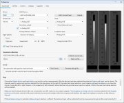
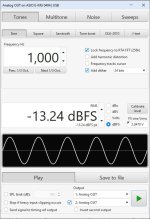
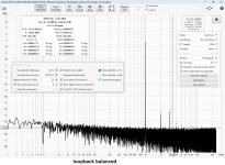
What settings for Generator and RTA Window you are using? I would like to compare my results with yours.Harmonic distortion is equal at the two input channels in my second EMU-0404 (also at the first).
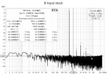
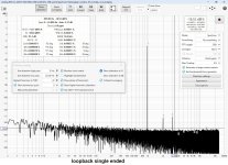
It was with generator at 0dBFS, 256k FFT length, Rectangular Window, no averaging. But there was Jan Didden's Autoranger set to -12dB btn soundcard Out and soundcard In. Connection was balanced TRS.
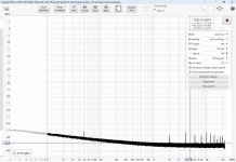
Now if you want to compare, I attach measurements without Autoranger. But for to achieve the same input level, I attenuate the Generator out.
George
Now if you want to compare, I attach measurements without Autoranger. But for to achieve the same input level, I attenuate the Generator out.
George
Attachments
- Home
- Design & Build
- Equipment & Tools
- E-MU 0404 USB 2.0 and some "artifacts peaks" on left channel