I built a nice little benchtop power supply from the Velleman kit K8042. Because I know benchtop power supplies are a staple for many DIY'ers I thought I'd post my results and suggestions.
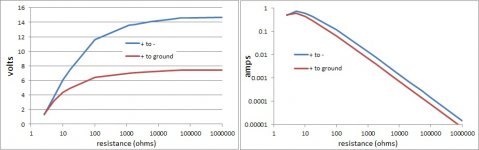
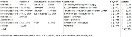
The Velleman K8042 is a small, inexpensive low power (less than 1 amp) symmetric DC power supply. Which means it has three outputs, positive, ground, and negative. Voltage from each output to ground is controlled separately through its own trimpot and its own regulator (LM317 and LM337). So, for example, one could set the positive terminal to 10V, and the negative terminal to -5V for 15V, with an offset of 2.5V. The first figure is a pair of graphs plotting maximum voltage (both trimpots turned all the way clockwise) vs. load (a resistor). This is with a 10VAC transformer rated at 6VA. According to the instructions, up to a 22VAC transformer can be used for an output of 18VDC. I plotted positive-to-negative and positive-to-ground separately. The I calculated I from I=V/R. I don't have an amp meter. The second attachment is my BOM.
Things I liked:
- It's super easy to build. The instructions even tell the builder how to solder, and identify the correct pole of an electrolytic and diode, and how to wire a transformer.
- Small PCB
- separate regulation of positive and negative outputs.
- inexpensive
- Extras are not included, keeping the cost down and allowing the builder chose heatsinks (for the regulators) and transformer to suit his/her needs.
- An optional heatsink specifically designed for this kit is available, though I didn't use it.
- Ripple was not visible on my oscilloscope. VAC was always less than 1% of VDC.
- The trimpots are single turn, making fine adjustment of voltages difficult.
- When the load or the set voltage is changed, the voltage drifts toward its final value. It can take up to 30 seconds to stabilize.
- I found the voltage from positive terminal to ground (negative to ground left open) was unstable at 5V when connected to a real world circuit (a DAC). Setting positive-ground and negative-ground to +2.5V and -2.5V and using those terminals solved the problem. Positive-ground is also stable with a simple resistor as load.
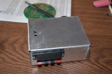
- Would have used a larger chassis with easier access. It took me more time to get the kit into the metal box than it took to build the kit.
- I only used my 10V transformer and small heatsinks because I had them leftover with no plans for them. If I were to go through the trouble of this build again, I would use a higher voltage transformer and the optional Velleman heatsink.
Attachments
Last edited:
You can replace the pots with 10 turn type for fine adjust or dual pots for dual tracking. This is a good circuit, it's in the data sheet for the regulator.
Manual for kit.
http://www.luedeke-elektronic.de/shop/vellemann/k8042.pdf
Manual for kit.
http://www.luedeke-elektronic.de/shop/vellemann/k8042.pdf
An externally hosted image should be here but it was not working when we last tested it.
- Status
- This old topic is closed. If you want to reopen this topic, contact a moderator using the "Report Post" button.