Hello Goran
Thank you for the very nice work making the comparisons.
Would you be able to use some leftover crossover parts and construct the RLC emulator that I have discussed in this thread? You would use the WT2 to accurately measure the inductor and capacitor at 25 Hz and then plug those values into the spreadsheet on this thread.
Then test Fs and Qt for this accurately characterized emulator and report the results of the closeness to actual Fs and Qt.
If you can, please get the Fs to be less than 20 Hz. The high end car audio woofer that is my current "torture test" has an Fs of 17 Hz at Xmax.
Best regards,
woofertester
Hello Goran
Thank you for the very nice work making the comparisons.
Would you be able to use some leftover crossover parts and construct the RLC emulator that I have discussed in this thread? You would use the WT2 to accurately measure the inductor and capacitor at 25 Hz and then plug those values into the spreadsheet on this thread.
Then test Fs and Qt for this accurately characterized emulator and report the results of the closeness to actual Fs and Qt.
If you can, please get the Fs to be less than 20 Hz. The high end car audio woofer that is my current "torture test" has an Fs of 17 Hz at Xmax.
Best regards,
woofertester
What could be better than testing real drivers!
")
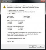
Actually I've tried to measure the artificial test load as you described and while it works perfectly in WT3 tester I always receive an error message in WT2 similar to the attached picture.
I've tried to change the Cap and resistance values, but it doesn't change anything. The coil is 6.6mH with an internal resistance of 0.45 Ohm.
I don't get this kind of errors in WT2 when I measure real drivers.
Regards
/Göran
Attachments
The reason to construct an emulator is that the T/S parameters of your real drivers are unknown. To evaluate test equipment requires a standard. The emulator is a DIY standard to test the test equipment.
The warning that you get from the WT2 indicates that the voice coil inductance of the emulator does not have the non-linearity of an actual speaker voice coil. You can change the model from a 4-part voice coil inductance to a simple Le model. For a real speaker, the 4-part voice coil inductance parameters create a very accurate model.
In your WT2 software you do this
Options -> Le Test Method
There are three choices
Classical 'Bare Tank'
Two Point Frq Dependent Le
Three Point Frq Dependent Le
Choose Classical 'Bare Tank' and click OK.
Now you can test the bare tank circuit that is the emulator. I suspect that the WT3 does not extract the 4-part frequency dependent Le model parameters but I don't know for sure. That would be why the WT3 does not throw an error when it tests a bare tank when it is expecting a speaker.
When you test a real speaker change the option back to frq dependent Le.
Thanks Goran for taking the time and expense of running those comparative tests. In reading thru your comments on each of the attachments, I noticed who didn't address the glaring differences in Le. Driver inductance is also an important T/S parameter when designing xo's. To me, at least, the WT2 results were much more closely aligned with the mfgr's specs (bold column). The striking departure of the WT3 Le data from mfgr specs is notable.
Thanks Goran for taking the time and expense of running those comparative tests. In reading thru your comments on each of the attachments, I noticed who didn't address the glaring differences in Le. Driver inductance is also an important T/S parameter when designing xo's. To me, at least, the WT2 results were much more closely aligned with the mfgr's specs (bold column). The striking departure of the WT3 Le data from mfgr specs is notable.
You hit the nail on the head. The WT3 cannot measure Le properly due to the methodology they employ. A sweep/chirp will never accurately extract Le nor accurately follow the peak of the curve where Qt is measured. The WT2 has those signals to be "competitive" but I would never use the results of a sweep/chirp to build a system. Why use inaccurate T/S parameters?
In addition, Le is really a very old concept. All of the "good" test gear nowadays measures the 4-part non-linear inductance model that was discovered by Celestion. The WT2 also can plot the modeled impedance curve with the 4-part inductance model as well as the simple Le model. When you model and measure in-air response, the output of the speaker is different with the 4-part inductance model compared to simple Le. We have a FAQ article on the exact match of modeled versus measured in-air response with results from the WT2 T/S parameters. The in-air measured curve sits exactly on top of the modeled in-air response curve.
I think that it is possible that they are using 1kHz for the calculation but the impedance that they are looking at is wrong because of the fast sweep. Think of it this way. The inductor stores energy and returns energy. If you are sweeping quickly from 1 Hz to 20kHz, by the time you measure 1kHz you are way past 1kHz. The same is true for Fs. There is a heck of a lot of energy stored at Fs. If you sweep past it there is no way to excite it and measure it accurately.
If you want accurate, it takes time. Google Fourier Uncertainty Principle for some light reading on the topic.
If you want accurate, it takes time. Google Fourier Uncertainty Principle for some light reading on the topic.
Goran's tables suggest the WT3 is designed to measure Le @ 10 khz. This doesn't make any sense to me simply because that freq. (these are woofer testers after all) is WELL out of any normal woofer's pass band.
In WT3 it's selectable between 1kHz and 10kHz. I used both for comparison.
Thanks Goran for taking the time and expense of running those comparative tests. In reading thru your comments on each of the attachments, I noticed who didn't address the glaring differences in Le. Driver inductance is also an important T/S parameter when designing xo's. To me, at least, the WT2 results were much more closely aligned with the mfgr's specs (bold column). The striking departure of the WT3 Le data from mfgr specs is notable.
Yes, the WT2 is clearly a winner when it comes to accuracy.
I will use both products in my next loudspeaker project to see how much the better WT2 measuring accuracy affects the design.
I regularly do both just to see the before and after. For design you use the after break-in parameters.
As a point of discussion, I have a 12 inch Tantric woofer that has an excursion in excess of 3 inches pk-pk. At rest the Fs is 32 Hz. At full excursion Fs is 17 Hz. It takes a couple of minutes for the surround to cool down but eventually the Fs returns to 32 Hz when using the WT2.
This is why we make the WTPro. Most people have no idea how different a speaker is at Xmax compared to at rest.
I had seen in lots of you tube videos of speaker production factories like Eminence & many others. They randomly test raw drivers just after every production batch before packing. They do not run them till break in.
I have few questions here....
(1). What is the accepted industry standard or in other words ... which would be considered the accurate or actual t/s specs of any driver as to be specified by the manufacturer in their spec sheet , will it be after break in or before break in ???? .
(2). What are the conditions required when testing thru WT2 .... I mean driver mounted or unmounted, driver positioning & placement during the test, environment criteria ..... in room, outdoors, anechoic chamber etc. Any specific environmental conditions as to room temperature or relative humidity.
Vivek
For a manufacturer, they want to know if the driver was built correctly. The test is a "pass/fail" and not how it will play in your design. You break in and test so that you know how it will play in your design.
Break-in will not radically change the volume of your box nor the tuning frequency if it is a vented system. You break in the speaker to minimize the errors in the final tuning.
Delta mass requires that the speaker be horizontal unless you stick the mass to the speaker which can cosmetically ruin some speakers.
You must not set a speaker on its magnet structure if it is vented. This will cause the Fs/Qts to become wrong for the measurement. We recommend that you suspend the speaker with bungee cords. This decouples the speaker from vibrations of open/close door, walking, etc. See this
woofertester.com
If you have a concrete floor, you can set the speaker on blocks that allow air to get to the vented pole piece. I use scrap wood from cabinet projects.
For a manufacturer, they want to know if the driver was built correctly. The test is a "pass/fail" and not how it will play in your design. You break in and test so that you know how it will play in your design.
Forget the manufacturers. What if anybody build their own driver ?.
What if I build or fabricate a raw sample prototype driver from scratch ...... motor assembly to frame to cone/spider/voice-coil/dust-cap. Driver is ready with unknown parameters. To know about its t/s values kindly advise, What next ?. What shall I do next ......... ??? , run a break in before measuring thru WT2 ???.
Vivek
It is always advisable to break in a driver before measuring. You will be using it broken in for years, so you should measure it broken in.
When I break in a driver, I use a WT2 line output set at 15 Hz. I use an amplifier with a volume control. I adjust the volume for full Xmax excursion. I use a laser pointer aimed at the dustcap to eyeball the measurement of excursion. I also listen for the voice coil tapping the back plate and adjust to just below the tapping sound.
I run the speaker at Xmax for at least 1 hour. I let the speaker cool for at least 1 hour. Then I test the speaker for T/S parameters.
If I have time, I will run the speaker at Xmax 8 hours and let it cool over night.
It is always advisable to break in a driver before measuring. You will be using it broken in for years, so you should measure it broken in. When I break in a driver, I use a WT2 line output set at 15 Hz. I use an amplifier with a volume control. I adjust the volume for full Xmax excursion. I use a laser pointer aimed at the dustcap to eyeball the measurement of excursion. I also listen for the voice coil tapping the back plate and adjust to just below the tapping sound. I run the speaker at Xmax for at least 1 hour. I let the speaker cool for at least 1 hour. Then I test the speaker for T/S parameters. If I have time, I will run the speaker at Xmax 8 hours and let it cool over night.
Does this rule also applies for fixed edge full-range, lower & upper mid-range speakers ?. How would anyone determine the break in frequency for fixed edge full-range & mid-range drivers, and for how long ?
Last edited:
Does this rule also applies for fixed edge full-range, lower & upper mid-range speakers ?. How would anyone determine the break in frequency for fixed edge full-range & mid-range drivers, and for how long ?
I use 15 Hz because it is below Fs and at 15 Hz the speaker is easier to excurse with the least power and the sound does not destroy your hearing. Try being in a room with a speaker moving 3 inches peak to peak at 1kHz. At 15 Hz the speaker will move much more like a piston than at 1 kHz. You are breaking in the suspension and not the cone. So, a frequency where the cone is not breaking up is preferable in my opinion.
You can use any frequency you wish that allows you to break in the speaker. I choose what works for me.
The spider is the part that changes the most. For a speaker whose compliance/Vas is dominated by the surround, break-in will affect the speaker less.
There are no industry standards for what you have been asking. There are only some accepted practices and knowledge gained by study and trial and error.
There is a school of thought that holds forth that the speaker is not going to be in a much different box after break-in than before. This will be true for a closed box system. Maybe not so much for a vented box system.
- Status
- This old topic is closed. If you want to reopen this topic, contact a moderator using the "Report Post" button.
- Home
- Design & Build
- Equipment & Tools
- Faulty Dayton WT3...