In general, the meaningful harmonics will be from 2 up to 10, so a measuring bandwidth of 10X the fundamental is customary. Some industrial, broadcast, telephony, and military systems specify standard low-pass frequencies of 30kHz and 80kHz when measuring in the audio band, and 400Hz high-pass filtering is very helpful in reducing hum and noise in various radio and telephony measurements, not to mention high-end audio gear.
I found an old Tektronix 7L5 Spectrum Analyzer to look at the Reading Monitor Output. There was a strong birdie at 48.5kHz when the Monitor was on. That was with a 22kHz filter on the distortion. Monitor on or off didn't make much difference. The options can set it at 22kHz, 30kHz, 80kHz or >500kHz. Those filter selections revealed harmonics of the 48.5kHz and an increase in the residual distortion at low signal levels.
My spectrum analyzer shows a fair amount of junk (spikes of 10 to 20 db above the noise floor) in the 40 to 50kHz region. I attribute these to noise from switchmode power supplies for my computer monitor, computer, battery chargers, and fluorscent lights. I don't know if they are radiated (EMI) or carried on the power lines, or both. The trouble with the hp8903 is that they are counted - summed into the THD + noise calculation. When looking at low distortion devices such as preamps, they swamp the THD result. Now I just use Dick's twin-t to null the fundamental about 50db and then read the fundamentals off the spectrum analyzer and do the THD math manually. This is one of several reasons why most folks say that a THD number alone is not very informative.
Ken
Ken, I experience the same thing with my setup.
I blew up a plot with the input of the analyzer hooked to an amp (which was turned off) and started counting harmonics of 60Hz and found that out beyond 3KHz it was all related (as far as I was confident in my interpolation).
If I do a straight loop-back test I don't see the noise.
I've isolated some of the noise to specific sources in my house by turning them off and back on while observing the results. One florescent lamp in the den in particular gives me a lot of noise around 16KHz-23KHz.
Florescent light efficiency peaks at around 15kHz so expect to see more of that in the future.
I'm unclear on how to get a percent distortion number from a spectrum analyzer. -40dB would be 1%, -50dB would be about 0.3% but how do you add the two together? Simple addition of root sum of the squares?
Looking at the monitor output of a distortion analyzer, the root is nulled out so there is no reference, and it's auto-scaled so you have no idea of the gain. But you can see a lot of harmonics that otherwise would be burried. The 7L5 only has about 76dB between the Reference level and the noise floor so that's 0.02% or so.
@loudthud -- the scaling and reference level issues depend on the analyzer. The HP 339 is not a problem, for example, while the 8903 is. But the analyzers have their own issues with noise and self-distortion, so some care is needed in analyzing results at the monitor output.
The dynamic range issues of the 7L5 for example can be dealt with by using an active notch filter to reduce the fundamental without losing track of the reference level for remaining distortion and/or noise products. A good spectrum analyzer is a great thing to have -- wish I had a 7L5 -- just not in the budget right now....
The dynamic range issues of the 7L5 for example can be dealt with by using an active notch filter to reduce the fundamental without losing track of the reference level for remaining distortion and/or noise products. A good spectrum analyzer is a great thing to have -- wish I had a 7L5 -- just not in the budget right now....
Ken, I experience the same thing with my setup.
I blew up a plot with the input of the analyzer hooked to an amp (which was turned off) and started counting harmonics of 60Hz and found that out beyond 3KHz it was all related (as far as I was confident in my interpolation).
If I do a straight loop-back test I don't see the noise.
I've isolated some of the noise to specific sources in my house by turning them off and back on while observing the results. One florescent lamp in the den in particular gives me a lot of noise around 16KHz-23KHz.
When I feed the distortion analyzer with a signal from my low distortion signal generator I don't have the spurious noise(s). Only when I feed the amp from the generator then to the analyzer I get the noise(s). I believe a few things are at work here, one I haven't done a good job with emi shielding of the DUT (it's current open air), nor the power supply, and, two, I may have cable impedance mis-match with the analyzer which allows the cables to pick up the noise. Ultimately, the test for the finished amp will be to have a signal that is as clean as the signal generator signal.
Ken
I'm unclear on how to get a percent distortion number from a spectrum analyzer. -40dB would be 1%, -50dB would be about 0.3% but how do you add the two together? Simple addition of root sum of the squares?
The 7L5 only has about 76dB between the Reference level and the noise floor so that's 0.02% or so.
Regarding your second statement, my analyzer has 85db of headroom, but, here is the trick: Build Dick's twin-t notch filter to reduce the fundamental frequency by 50 or 60db, then your harmonic fundamentals will show up - the noise floor will drop. My analyzer has a noise floor of approximately -125db so, with a 50 db fundamental null, I can see the full noise floor and any harmonic fundamentals that rise above it. The second part of the deal is to make sure that your DUT is putting out exactly 1vrms or 0db. For a preamp type device, what I do is first hook the DUT up to the analyzer and adjust either the signal generator and or the preamp volume control until the fundamental reads 0db. I turn off the DUT, hook it up to the twin-t, hook the output of the twin-t to the analyzer, turn on the twin-t and then the DUT. Adjust the null of the twin-t to something at or greater than 50, then run the calibration sequence of the analyzer, then run the averages function of the analyzer a stable mean average of 50 and viola you have your spectrum.
Gotta go... how to THD calc later
Ken
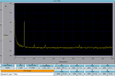
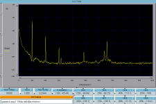
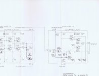
not knowing where else to post this, I figured here is probably as good a place as any. I am making some update modifications to an old Quan Tech 2173C Transistor Noise analyzer. I need to update an amp section (image 1 is the schematic) so that it will work with JFETs. I removed the amp section and powered it up with my lab bench supply to make a baseline measurement (image 2). A pretty clean amp and spectrum, all with the board unshielded out in the open air. I then replaced all the carbon resistors with metal film Dale Rn55's figuring that I could improve the noise floor a bit with quieter resistors. Well no such luck, with the same identical setup, measured early in the morning just like the prior measurement, things got much worse! (see image 3).
I've been thinking about this all day, and believe that it might be the ferrious quality of the Dale resistors that pick up the EMI far more readily than the non-ferrious carbon resistors.
So today I ordered up some non metalic Halco resistors and will install them to see if thing return to the baseline. If that doesn't work, I will put in some NOS Allen Bradley's. Any other thoughts would be welcome.
Ken
Attachments
Just to be clear, the dale resistor leads don't seem to be ferrous, only the body of the resistor, the carbon resistors are not attracted to the magnet. I will also do a good job of cleaning the flux off the board and retest, just in case.
Ken
All of the resistors in the Quantech are tested for noise. You won't accomplish much trying to second guess Quantech's choices. Good metal film resistors will be more than good enough. Your noise issues are probably environmental, one of the down sides of testing on a bench. You are limited by the device noise. The noise of the preamp will not limit measuring any FET you can buy since it uses gain from the FET so unless the noise of the FET is below .1 nV/rthz it probably won't matter. There are a few locations that are noise sensitive but most metal film resistors will be OK even there.
I'm not sure what you need to change to support FETs. Every one I have played with (3 now) have supported FETs. There is a switch on the front panel that selects fet-bipolar as I remember. I'll dig out the manual tonight.
The parts that age are the electrolytic caps. Current ones are orders of magnitude better than the originals. If I were to invest the effort it would start with new caps on the supplies (not a lot bigger than the originals or some other problem will surface).
Demian,
My Quan Tech is older than jfets, no switch on the front. I'm updating the device to include the switch. It appears to be a pretty simple modification.
I was just struck by how different the spectrum was with the resistor change, when tested under identical conditions. My theory is that the ferrous quality of the resistors makes them subject to significant emi pick up.
Ken.
Ken, that's a huge difference in the plots and I can't believe that the change is solely due to changing resistors, especially to metal films. Something else is going on here. I assume you're using good old fashioned 60-40 tin-lead solder? Mixing Lead-free with regular can be a nightmare....
Hi Dick,Ken, that's a huge difference in the plots and I can't believe that the change is solely due to changing resistors, especially to metal films. Something else is going on here. I assume you're using good old fashioned 60-40 tin-lead solder? Mixing Lead-free with regular can be a nightmare....
Yes it seems like too big of a swing. I hope it doesn't indicate over heating of the transistors during the desolder. Using cardias eutectic solder.
Ken
Help me with the plots. The noise floor seems to be around -110 in both. The first plot has a 10 KHz peak in it. Where is that from? The second shows a lot of harmonics from the peak and some 48 kHz and some 65 kHz. The latter two look like switching supply or monitor or CF noise to me.
Which preamp are you tweaking? There are three, depending on the current setting. Or is it the amp (Front cage 4th board from the left)? There is a fair amount of gain in front of the amp so noise there is not too consequential.
The calibrating oscillator runs at 4 KHz.
I would do the following- first put it back together and feed a signal into the noise cal test point at the transistor jig. Look at what comes out with a good transistor in the jig. A 2n3904 running at 100 uA should get down to 1-4 nV /rtHz or so at 1 KHz or less if the base resistance is set to zero. If you add a signal via the noise cal it will be processed and should be visible at the output BNC at around 10X the level it went in at. The input Z is 600 Ohms so measure at the noise cal terminal to get the gain right..
Do you have a manual? I may have a scan here if I can find it. The calibration is pretty straightforward, if you have a noise generator calibrated in mV/rtHz. Otherwise its more difficult to get everything aligned and meaningful numbers.
The manual I have is for serial number 203 and really old. The internals of John Curl's are the same and his is 20 years newer than the manual. The unit has a gate voltage control for setting a fixed gate bias. I pretty much never use that and use the drain/collector current to set the biases. For matching transistors you can connect a more precise voltmeter (DVM) to the gate (base) terminal (D4) of the base supply board and readout the voltage for a target drain current which would be the operating point. Its a very clean way to match JFETs.
edits-
My manual is definitely older than the one you are looking at. It does not have the switch or relay and the connections are not brought out of the card. Your unit predates the relay and switch. I'm not sure that prevents it from measuring JFets but if you are up for the changes have at it. The older drawing will help identify what changed (attached)
Your measurement software indicates that the THD+N went down with the change even though it doesn't look like it. The 10 KHz is also higher in the second plot for what seems to be the same signal level.
Attachments
Last edited:
Help me with the plots. The noise floor seems to be around -110 in both. The first plot has a 10 KHz peak in it. Where is that from? The second shows a lot of harmonics from the peak and some 48 kHz and some 65 kHz. The latter two look like switching supply or monitor or CF noise to me. .
The 10KHz peak is the fundamental frequency, it has gone through a notch filter (Dick's twin -T ) and is down about 50db - the amp output is at 1 Vrms. Using the notch filter drops the floor of the spectrum analyzer to about -130db.
I agree about harmonics being from environmental factors, like the switching supply. The interesting thing is that the board was relatively immune to these factors when first tested.
Which preamp are you tweaking? There are three, depending on the current setting. Or is it the amp (Front cage 4th board from the left)? There is a fair amount of gain in front of the amp so noise there is not too consequential.
It's Amp#1 as shown on the right side of your posted schematic. The manual I have is a bit newer than yours, yours exactly matches my board. My manual show things like the JFET switch, which is a part of the AMP #1 schematic. (not shown on your schematic - see lower left corner of AMP #1 schematic.)
The calibrating oscillator runs at 4 KHz.
I would do the following- first put it back together and feed a signal into the noise cal test point at the transistor jig. Look at what comes out with a good transistor in the jig. A 2n3904 running at 100 uA should get down to 1-4 nV /rtHz or so at 1 KHz or less if the base resistance is set to zero. If you add a signal via the noise cal it will be processed and should be visible at the output BNC at around 10X the level it went in at. The input Z is 600 Ohms so measure at the noise cal terminal to get the gain right..
Do you have a manual? I may have a scan here if I can find it. The calibration is pretty straightforward, if you have a noise generator calibrated in mV/rtHz. Otherwise its more difficult to get everything aligned and meaningful numbers.
The manual I have is for serial number 203 and really old. The internals of John Curl's are the same and his is 20 years newer than the manual. The unit has a gate voltage control for setting a fixed gate bias. I pretty much never use that and use the drain/collector current to set the biases. For matching transistors you can connect a more precise voltmeter (DVM) to the gate (base) terminal (D4) of the base supply board and readout the voltage for a target drain current which would be the operating point. Its a very clean way to match JFETs.
edits-
My manual is definitely older than the one you are looking at. It does not have the switch or relay and the connections are not brought out of the card. Your unit predates the relay and switch. I'm not sure that prevents it from measuring JFets but if you are up for the changes have at it. The older drawing will help identify what changed (attached)
Your measurement software indicates that the THD+N went down with the change even though it doesn't look like it. The 10 KHz is also higher in the second plot for what seems to be the same signal level.
I would be interested in a scan of your manual if you can find it.
Thanks for the tip on transistor matching!
Regarding modification for the JFET switch, the board came with the D(4) circuit and the connector is empty at that location, so, the modification will be quite easy. Regarding the THD+N, it's read off my HP8903A, I don't know if any filters were turned on, nor to I particularly trust it. I normally hand calculate the THD from the Harmonics - note that I am able to extract and display them from the spectrum data.
Ken
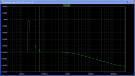
So I made a quick check with a spice simulation using 2N5401 and 2N5551 Cordell models. The FFT plot is quite similar to the second spectrum plot. I don't know what to think... maybe the first plot was a total fluke.
I thought that maybe I had run the first plot at a lower input voltage, but, the voltage measurement shown on the plot is taken from the HP8903A and it reads 1vrms on both plots.
Given the spice results, the quan tech will probably run fine as modified, but, I am still going to try to reproduce the first spectrum result. I will build a replacement board and try populating it with carbon resistor just like the original. Looks like a Fairchild SS8050 or BC63916 are both reasonable subsistution for the 2n3644 device.
Ken
Attachments
- Status
- This old topic is closed. If you want to reopen this topic, contact a moderator using the "Report Post" button.
- Home
- Design & Build
- Equipment & Tools
- How Distortion Free are the Distortion Measurers?