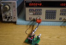
Very nice performance coming out of the input board. For a -104 dB reading on the display the monitor output looks correct after the 80dB of post-notch gain. It is easy to see what frequency components need to be improved downstream, including fundamental rejection.
For now, I will hold off on accepting your offer for the modified input board. Thank you for offering; I may like to test it later. I need to get some things set up here in my lab first and run some baseline measurements to capture the present state with my equipment. I still have a few equipment gaps to fill.
Did you manage to get AD797s to work in all locations in the instrumentation amp? If the DC performance of the first two op-amps looks good enough, we may be able to eliminate U4 and U7 and bypass the switch with permanent jumpers. These are used for DC LEVEL mode only.
What light bulbs did you use to replace the 10k resistors?
The filter caps dry out and the AC ripple increases. There is a low line voltage trip circuit on the power supply board that monitors the unregulated +5V supply to the CPU and when it falls below an adjustable threshold, it pulls the Non-maskable interrupt on the processor halting its operation. This prevents the processor from running amok during brownout conditions and overwriting the battery-backed-up RAM. When the cap begins to fail, the excess ripple may prevent the unit from starting up and this is a classic indicator that the power supply caps need to be replaced.
Very nice performance coming out of the input board. For a -104 dB reading on the display the monitor output looks correct after the 80dB of post-notch gain. It is easy to see what frequency components need to be improved downstream, including fundamental rejection.
For now, I will hold off on accepting your offer for the modified input board. Thank you for offering; I may like to test it later. I need to get some things set up here in my lab first and run some baseline measurements to capture the present state with my equipment. I still have a few equipment gaps to fill.
Did you manage to get AD797s to work in all locations in the instrumentation amp? If the DC performance of the first two op-amps looks good enough, we may be able to eliminate U4 and U7 and bypass the switch with permanent jumpers. These are used for DC LEVEL mode only.
What light bulbs did you use to replace the 10k resistors?
The AD797 is tricky to use and it needs some impedances in specific places or its unstable. The LME49710 is way cheaper as well. The AD797 works well for the differential amp. I'm sure the other two amp could be upgraded but its more involved.
I'll need to look up the light bulb. I was looking for a 3W 220V lamp. Nothing small and neat available on this side of the pond. What I wound up with is pretty crude but it works.
Stable FET opamps are available and not expensive so eliminating them is not a huge issue. It seems all the new low noise opamps are quite stable. the LT1115 is actually a selection of the LT1028, also an ultra stable low noise opamp. They did not work as well as the LME on the input buffers.
I may be able to lend you a GPIB interface if that would move things along. I actually have several.
The notch is not real stable. It seems to drift with time, temp and the phase of the moon.
I also have an issue with AC leakage to the chassis. And I noticed the DCR to ground from the two ground posts on the front is different. This makes test setup a moving target at times. All this can get sorted out.
I have added on all of mine an output from the input board output, pin 27, that I use as an input monitor. Its isolated with a resistor. It has proven really useful.
This looks very interesting and the approach is much like the recent upgrades to the HP339A. If the DIY'er can easily get these models, it will be a great help. We all learn from others and this is a great opportunity for me to learn more and this time direct from the designer ")
Thank you, and Welcome to our corner of the world !
Richard Marsh
Thank you, and Welcome to our corner of the world !
Richard Marsh
Last edited:
I just saw a 1121 for sale at eBay for over 5000 dollars !! .01% lowest range. That seems a little bit on the (very) high side! What is the typical cost of a used one?
THx-RNMarsh
The Stanford Research Audio Analyzer (Stanford Research Systems) is in the same pricing vicinity, but close to SOTA!
I sold an 1120 for around $300 a few years back.
I just saw a 1121 for sale at eBay for over 5000 dollars !! .01% lowest range. That seems a little bit on the (very) high side! What is the typical cost of a used one?
THx-RNMarsh
Has it been recently cal'd or some else special?
I have never payed over $300 for a Boonton and I have 5 at last count. The current new price is quite high and since its qualified for some MIL projects etc. it may be "valid" but not for general purpose. A lot were retired from military service and pretty cheap which makes them attractive. They were part of some involved communications test systems and changing a qualified system can cost way more than paying $5K for the one that is qualified.
More will appear at more reasonable prices. However using the architecture and designing a replacement that would build on the strengths and use newer solutions is a better long term direction.
More will appear at more reasonable prices. However using the architecture and designing a replacement that would build on the strengths and use newer solutions is a better long term direction.
A few quick updates on my tweaking of the 1121/1120 I have.
First I have confirmed that the LME49710 in U5 and U8 works fine. I tried bypassing the analog switch, remove U4 and U7 and jumper 2-3 and 6-7 on U4 and the DC doesn't go nuts indicating the input bias on the LME49710 is pretty low. The DC seems accurate without recal, maybe more than with the TL072. I will do a recal and check everything.
On the two boards I have one seems to have higher distortion on the 3-16V range, especially at the 16 volt level. After checking everything all that is left are the divider resistors it seems, R8, R9, R10 & R11. On the better performing board they are much larger parts so maybe it is just limitations of those resistors.
Finally, I found that CR13 prevents negative voltage measurements. Its not on one board and is on the other. Perhaps Mike can explain its presence. I was really lost on that issue for a while.
Went further on this road. Looking at the circuit I figured out that to get the best DC accuracy it would need a FET input opamp for U5 and U8. The specs for the OPA134 suggest that is would have low enough noise and distortion that it should work. So I swapped in OPA134's. They do work fine. I get down to .0006% THD w/ 30 KHz filter and the DC meets spec. with U4 removed and jumpered. The DC accuracy is in the .1% -.2% range. Next big goal is to improve the oscillator + power amp.
Hi Demian,
It has been a while since I checked in as I have been away due to demands from my day job invading my hobby time. In the mean time I have been adding to my test equipment and parts supply and have started up again with making tweaks to the Boonton 1121. I noticed you tried to get rid of the DC front-end circuit before the instrumentation amp. I did the same thing before I read your post. That circuit was always a potential issue and violated my desire for simplicity (KISS principle). I needed the perfect op-amp back in the 80's and could never find one. I recently tried the LME49710s and they seem to work pretty well from an DC offset, distortion and noise standpoint but I have not looked to see whether there are any negative impacts from the modification yet. I will order some OPA134s and try them too and will let you know what I find. So far I have been focusing on the distortion analyzer side and I have some nice progress to report.
I picked up a SG505 for my bench and an ultra low distortion oscillator on Ebay from Victor. With these in hand I began working on the Notch Board. It is like peeling an onion. I always knew there were two big issues with the Notch: Fundamental feedthrough and 2nd harmonic distortion from the 4-quadrant multipliers. I improved both of them and can see a consistent <0.00050% without making any modifications to the Input and Filter boards. Even at that some of what I am seeing in the Monitor output is power line hum, but I do not have a good 400Hz high pass filter to get rid of it. I will have to work on one. The second harmonic is significantly lower now. I will get out the FFT analyzer and do a old vs. new comparison later, but I wanted to give you and others some mods so you we can work in parallel. I have an 1121, an 1120 S/1 and a spare set of analyzer boards so I can make some "before" and "after" comparisons and then see if the modifications improve all three sets. I also recently acquired a Boonton 1110 for $99. It was in beautiful shape and not working, but I fixed it relatively easily. I will use the 1110 when I get to the oscillator and amplifier sections. The 1110 is nearly identical to the 1121's source side.
Next I will list the modifications to the Notch board.
First of all, the fundamental feedthrough on the stock 1120 and 1121 was not as good as it could be and was caused by chopper noise getting into the Tune and Balance integrators. This caused an offset affecting the null with rising frequency. Lowering two resistors R42 and R43 from 3.01k to around 600 ohms reduces the chopper energy significantly. A second modification is to change U2 from a NE5532 to a LME49720. The improved DC performance of the 49720 will take away a major offset component driving the need for adjusting Tune and Balance offsets. After nulling the fundamental you will notice that the two pots are nearly centered now. As a result, you can reduce R52 and R54 from 10 ohms to 2 ohms. This will make it easier to adjust for best rejection of the fundamental.
With auto Tune and Balance fixed, I moved on to reducing the residual 2nd harmonic. There were two potential culprits: FETs and Multipliers. I had experimented with higher performance multipliers back in the 80's and saw some nice improvement, but I want to stick with what can be easily changed by scaling values and swapping components. No cuts or jumpers would be nice for everyone trying this at home.
What I found was that most of the 2nd harmonic was caused by poor scaling of the multipliers X vs. Y inputs. I chose to lower the AC component while increasing the DC component proportionally. I tried a scaling of 4x so R59, R60, R67 and R68 go from 49.9k to 200k and R62 and R63 go from 80.6K to 20K and R64 and R65 go from 100k to 25k. BTW, this rescaling of the multipliers should improve the Source oscillator as well. It is important to maintain the same X*Y product because the software expects it and it could cause tuning issues if the scaling is not done correctly.
All relatively easy changes, but I think you will find a significant improvement, not just at 1 kHz but all the way up beyond 100 kHz.
Let me know how you do.
In a separate post I will explain the changes made on the Analyzer side to create the 1121 from the 1120. This will clear up the confusion regarding the diode messing up the DC level measurement on the Input board and other issues to watch out for when interchanging boards between the two versions. It turns out that the 1121 I have had some wrong components in it from an 1120 assembly. May have been a factory error!
Thanks,
Mike
Mike:
I had figured you got sidetracked by "real work". I am in the midst of a tidal wave of the same. However to confirm my informat tests of the input board showed that it contributes very little distortion with the changes I tried. What I did to test was route from Victor's oscillator (battery powered) through the input board and out to the Shibasoku and essentially got down to the Shibasoku residual, in the range of -113 dB THD, when the levels are all optimum.
I will try your enhancements as soon as I get the bench clear of paying work. Hopefully the next week or so.
The 400 Hz high pass filter limits the performance to about .002% or -96 dB. No amount of opamp magic will improve on that. Bruce Hofer suggested a matching network for the - input on the opamps that would get another 20 dB on Sallen Key filters. Its in this presentation, which is very good: http://www.ap.com/download/file/704 I have been tempted to really redesing the filter but no time. I have a layout for expresspcb pc board to make more filters that can be built to be any of several of the filters. The blank boards are in the in-box of my round tuit.
Demian,
No rush, I am continuing to dig deeper into uncovering other improvements now that I have some equipment on my bench. I feel like I am still in the "crawl" stage of "crawl - walk - run" sequence.
Thanks for the info on the Sallen-Key filter design from th AP presentation. I will have to try it out. Got more parts on order...
I have been running the 1121 for days now and the fundamental rejection seems much more stable with these new modificaitons. Makes sense since the primary culprit was the NE5532 offset voltage drift. This is an example of why I have always had an aversion to designing with poteniometers. If the thing you are adjusting is not stable, what good does it do to use a pot to correct it? Also many pots are unstable by themselves.
Thanks,
Mike
Mike:
Updates so far on my efforts. I rescaled the offset per your instructions. In the process I discovered that U10 is critical to the nulling circuit. I had swapped the Harris opamp that was in it for something else that had excessive offset. I did confirm that an OPA627 will work but its not a good option at nearly $30. Put back the Harris and it all nulls fine and adjustable with 1 Ohm for the dividers R52 & R54.
U10 has two polarized caps on AC signals. I would think replacing them with nonpolar caps would be an improvement. I also see a mismatch in the DC resistances on the two inputs. It could add to any offset at that stage.
I made the change to the multipliers but I seems to have gone backwards somewhere. I can't get below .002%. Looking at the schematic it seems your suggestions actually swap who was controlling. The smaller resistors get increased by 4X and the larger reduced by 4X. Is that the correct direction? Is there something else I should be checking?
More updates:
I sorted out some mistakes and shortcuts I took and I have most everything working. However the board with the changed values for the multiplier has higher 2nd harmonic than the one without. My next step will be to swap the active parts involved- U1,2,3,12,10 to see if it affects the output. I may swap the multipliers first-U17 and U18 to see if they are causing a problem.
The board with the chopper mod but without the multiplier mod gets to .0005%. The one with the multiplier mod does not get below .0012%. The culprit is the second harmonic.
Any suggestions?
- Home
- Design & Build
- Equipment & Tools
- Boonton 1120/1121 Distortion Analyzer tweaks