There have probably been twenty threads with people looking for a wattmeter. I'm surprised there aren't really any options - speaker designers do lots of calculations, but no measurements?
There is this, but it has limited bandwidth (up to 8kHz, according to the designer), and isn't really geared towards what I'm looking for, although its close: Atlantic Quality Design, Inc., The PM-150 Audio Power Meter If you have any other references, please share. I've looked, but don't see anything workable.
So what am I looking for? A way to measure average power being applied to a driver or speaker system. It will need to be wide bandwidth, 20Hz to 20kHz, and have a selectable range, maybe say 5W, 50W, 500W. There has been a little discussion on this forum already, but I'm going to pull the most important bit from Analog Designs RMS Applications Circuit, Section III:
http://www.analog.com/static/imported-files/design_handbooks/405029458307440275176Section_III.pdf I've highlighted the most important parts in red.
So this means no rms-to-dc converters, which have been suggested in other threads. Instead, I'm looking at analog mulitpliers AD534, AD633, AD734 or MPY634. I don't see any application note really specifying how to put together a wattmeter, but I suppose it is pretty simple. I'll try to draw up a schematic - I'm hoping that some of the real EEs will check it before I build it!
There is this, but it has limited bandwidth (up to 8kHz, according to the designer), and isn't really geared towards what I'm looking for, although its close: Atlantic Quality Design, Inc., The PM-150 Audio Power Meter If you have any other references, please share. I've looked, but don't see anything workable.
So what am I looking for? A way to measure average power being applied to a driver or speaker system. It will need to be wide bandwidth, 20Hz to 20kHz, and have a selectable range, maybe say 5W, 50W, 500W. There has been a little discussion on this forum already, but I'm going to pull the most important bit from Analog Designs RMS Applications Circuit, Section III:
http://www.analog.com/static/imported-files/design_handbooks/405029458307440275176Section_III.pdf I've highlighted the most important parts in red.
POWER MEASUREMENT
Introduction
In any circuit, the product of the voltage across and the current through a given load will equal the power dissipated through the load. Problems arise (and much confusion persists) when the load is not a pure resistance. Inductive and/or capacitive circuit com¬ponents introduce a phase shift between the voltage across and the current through a given load. This phase shift becomes more pronounced as the re¬actance of these components increase (as with in¬creasing frequency); they then become a greater por¬tion of the total impedance of the load. In a purely inductive circuit, the voltage will lead the current by 90 degrees; conversely, the voltage lags the current in a purely capacitive circuit.
Of Volt-Amperes, Watts, and Vars.
There are three primary methods for defining and measuring the (sine-wave) power dissipated in a given load impedance: apparent power (Pa), average power (P) and reactive power (Pr).
Apparent power, measured in volt-amperes, is sim-ply the product of the rms value of the voltage across a given load times the rms value of the current through the load. That is:
Pa = Vrms x Inns
Where V is in volts and I is in amperes. The volt-am-pere rating is often used in specifying electrical equipment since volt-amperes may be used to di-rectly compute the current requirements of indi-vidual pieces of equipment.
Average or real power, measured in watts, is equiva¬lent to the apparent power multiplied by the cosine of the phase angle separating the voltage and current waveforms. That is:
P = Pa Cos 0 = Vrms I„ns COS 0
Where V is in volts, I is in amperes, 0 is in degrees. Most commonly used, average power specifies the overall power consumption of a particular circuit, re¬gardless of the dissipation of its individual compo¬nents—some of which may be reactive. The cosine of the phase angle, 0, is also referred to as the power fac¬tor and is the ratio of a circuit's average power to itsapparent power. A highly reactive load exhibits a low power factor with a correspondingly low power consumption.
Because of the importance of defining power con¬sumption within individual reactive components in a circuit, a third power specification, reactive power was created. Reactive power, in vars. (volt-amp reac¬tive), is used to directly measure the peak power con¬sumption of individual inductive components in a circuit, even though their average power consump¬tion (ideally) is zero. Reactive power is very impor¬tant to electrical power companies since they must still supply this energy during a portion of every cycle, even though (on the average) no energy is actu¬ally dissipated.
Reactive power is equal to:
Pr = Pa Sin 0 = Vrins Irms Sine
Where V is in volts, I is in amperes, 0 is in degrees.
Practical Power Measurement
The fact that averaging is carried out in performing rms computation means that whatever phase infor¬mation existed in the original signal will be lost after rms computation; this fact precludes the use of rms converters for measuring power into nonresistive loads. Measurement of complex power is normally carried out using analog multipliers, since they will preserve the voltage/current phase information.
So this means no rms-to-dc converters, which have been suggested in other threads. Instead, I'm looking at analog mulitpliers AD534, AD633, AD734 or MPY634. I don't see any application note really specifying how to put together a wattmeter, but I suppose it is pretty simple. I'll try to draw up a schematic - I'm hoping that some of the real EEs will check it before I build it!
I think that a voltmeter is good enough. You probably wouldn't notice the difference in a VU type display that sensed voltage vs power with music signals.
If you are building an instrument for precise power measurement of single frequencies or steady state signals, that is different. I suppose you could use a voltmeter and a current sense resistor with another voltmeter on it and multiply their outputs together.
If you are building an instrument for precise power measurement of single frequencies or steady state signals, that is different. I suppose you could use a voltmeter and a current sense resistor with another voltmeter on it and multiply their outputs together.
Why not simply record the V and I (via CT or Hall effect) directly into two channels of a sound card and then process it to determine the power? Then you just need some simple interfacing to get it into the S/C, and I'm sure the software couldn't be all that difficult.
This would also allow you to easily record the result.
This would also allow you to easily record the result.
Thanks for the responses. You know, I'm tired of guessing. I want to know what real music is doing across a real driver. I also detest using computers, so I don't if there is any way to avoid it.
Here is what I have so far:
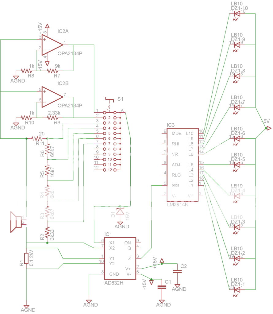
The chips I'm looking at are the AD734 multiplier and the LM3916 led display driver. They seem to be well mated - the first likes to operate around its 10V maximum output, and the second likes to operate around its 10V maximum input.
This setup has a 'native' sensitivity of 10W - ie, 10V on the output of the multiplier is equivalent to 10W across the device under test. I've included a switch to alter full scale sensitivity to 1W, 3W, 10W, 30W, 60W, 100W and 300W. The first two settings are accomplished by the two opamp gain stages, and the last 4 settings are allowed by the resistor divider network.
I've included a 15V zener diode on the input of the chip, as this is the specified maximum input. I then added R11 to prevent a short circuit on the amp when the zener is opened, which should hopefully just be momentarily.
The LM3916 is designed to mimic a VU meter, able to drive 10 leds which correspond to 0dB (full scale), -1dB, -2dB, -3dB, -4dB, -6dB, -8dB, -10dB, -13dB and -23dB. Combined with the 7 different sensitivity settings, this should provide a wide range of measurement capability.
If someone has a better suggestion for how to accomodate different sensitivities, let me know. I'm just making it up as I go. The other thing I didn't know about is whether the OPA2134 is a suitable opamp. I suppose it won't ever see a DC signal, so it should be okay.
Any input so far?
Here is what I have so far:
The chips I'm looking at are the AD734 multiplier and the LM3916 led display driver. They seem to be well mated - the first likes to operate around its 10V maximum output, and the second likes to operate around its 10V maximum input.
This setup has a 'native' sensitivity of 10W - ie, 10V on the output of the multiplier is equivalent to 10W across the device under test. I've included a switch to alter full scale sensitivity to 1W, 3W, 10W, 30W, 60W, 100W and 300W. The first two settings are accomplished by the two opamp gain stages, and the last 4 settings are allowed by the resistor divider network.
I've included a 15V zener diode on the input of the chip, as this is the specified maximum input. I then added R11 to prevent a short circuit on the amp when the zener is opened, which should hopefully just be momentarily.
The LM3916 is designed to mimic a VU meter, able to drive 10 leds which correspond to 0dB (full scale), -1dB, -2dB, -3dB, -4dB, -6dB, -8dB, -10dB, -13dB and -23dB. Combined with the 7 different sensitivity settings, this should provide a wide range of measurement capability.
If someone has a better suggestion for how to accomodate different sensitivities, let me know. I'm just making it up as I go. The other thing I didn't know about is whether the OPA2134 is a suitable opamp. I suppose it won't ever see a DC signal, so it should be okay.
Any input so far?
Nice circuit.
But it would be a lot nicer to get actual numbers on a display or meter, and maybe to be able to get numbers for both peak and average power (and in Watts, but maybe with dB as an option), and to also be able to have a "Max Hold" mode for both peak and average. (You can calculate an average power, as long as you do it after the multiplier, since the phase information is already accounted for, by then. You'd almost have to low-pass filter it, at least, to get a stable-enough display.) For the average power, it would also be nice to have a controllable-length averaging-time, or a controllable low-pass filter time-constant if it were all done with analog. Similarly, for the peak power, it would be nice to have a variable-reset-time peak-hold (max hold) display.
As long as I'm already asking for the moon, I might as well also ask for controllable upper and lower frequency window/bandpass limits, unless we're talking about wiring one of these directly across each driver, after the crossover circuits (but, adding connections across each driver and across the main input, that are all brought out to a 4x2 switch, might work, so we could look at either a single driver or all of them at once). Also, 22 kHz is probably not a high-enough upper limit. Or at least I wouldn't want to artificially limit it to that.
I thought about making a power-measurement device like that, a while back. I was going to try using two instrumentation amplifier-type circuits (differential amplifiers), one for current, across a low-value current-sense resistor in series with the positive input wire, and one for voltage, across both wires. I was leaning toward the AD633 analog multiplier chip, since I have used it in the past, and, it's relatively cheap.
At the time, I wasn't too worried yet about accomodating different input-power ranges. I probably would have eventually wanted it to at least be able to handle several different maximum power levels. But I'm not sure if the differential amps' maximum ranges would need to have been changed downward, for the lower power levels. i.e. For lower power levels, we could just ratchet the gain higher, for some scaling amplifier downstream, so that the inputs could always handle up to some fairly-high maximum design levels and not need to be adjusted, but any much-lower sustained power level would be better-resolved by adjusting things to use more of the full range of the A-to-D input (or whatever was being driven; even just a voltmeter (or maybe several of them) would work for a one-off with limited functionality, for personal use).
Maybe some sort of time-windowed peak-hold function (of the multiplier output) could have been used to automatically change the gain of the output-scaling amplifier. Of course, a manual switch could be used, instead, to set the output scaling.
Sorry to have blathered-on for so long, about all of that.
Cheers,
Tom
Hi,
the effort required depends on quite a couple of factors, for example:
- bandwidth
- precision level/error budget
- crest-factor
- power factor
- type of signal (single tone, multitone, noise)
- amount of harmonics
- type of sensors (especially the type of current sensors)
to name just a few.
If a lower bandwidth limit is allowed for, then Energy monitoring chips like ADE7953, or the ADE71xx and 75xx-family might be a good choice.
See App-Note AN-916 of ADI.
Depending on the requirements other solutions requiring more chips may be feasable.
ICs:
AD734, ADI8436, LTC196x (LinearTechnology), THAT2252, That4301, That4320 (ThatCorp), NTE1498 (NTE)
Literature:
AN-564, AN-916, "RMS-to-DC-Conversion-Application-Guide" and general notes from ADI.
AN-106, DN-339 from LinearTechnology
"True RMS Plasma VU-meter" at Audio Vu meter with IN13 or IN9 Russian nixie bargraph tubes
and many more.
You´ll quickly discover that there´s much more to precise power metering than just calculating VxI")
jauu
Calvin
the effort required depends on quite a couple of factors, for example:
- bandwidth
- precision level/error budget
- crest-factor
- power factor
- type of signal (single tone, multitone, noise)
- amount of harmonics
- type of sensors (especially the type of current sensors)
to name just a few.
If a lower bandwidth limit is allowed for, then Energy monitoring chips like ADE7953, or the ADE71xx and 75xx-family might be a good choice.
See App-Note AN-916 of ADI.
Depending on the requirements other solutions requiring more chips may be feasable.
ICs:
AD734, ADI8436, LTC196x (LinearTechnology), THAT2252, That4301, That4320 (ThatCorp), NTE1498 (NTE)
Literature:
AN-564, AN-916, "RMS-to-DC-Conversion-Application-Guide" and general notes from ADI.
AN-106, DN-339 from LinearTechnology
"True RMS Plasma VU-meter" at Audio Vu meter with IN13 or IN9 Russian nixie bargraph tubes
and many more.
You´ll quickly discover that there´s much more to precise power metering than just calculating VxI
jauu
Calvin
Youre schematic looks OK but I think that it's necessary to average the output of the multiplier with a low pass filter. I used a 470 kohm and 1 uF capacitor then an operational amplifier buffer to drive the moving coil meter. There is range selection for the voltage but no range selection for the current is that OK? Also you could add a resistor in series with the non inverting inputs of IC2A and IC2B for some protection. If the operational amplifiers survive they can't output more than 15 V so the zener diode, D1, shouln't be necessary.
Many years ago I designed and a friend built a Power Meter. It used a differential amplifier connected across the emitter resistors of the Power Amplifier to sense the current and a Motorola MC1495 analogue multiplier.
The results were interesting but possibly not that useful. The Power amplifier was capable of 300 W into an 8 ohm load and also included a clipping indicator. It was found the maximum reading on the meters was about 60 W when playing 'music' without clipping.
ETI magazine published a design for an audio power meter using an anlogue multiplier. It sensed the loudspeaker current with a series connected low value resistor as well. I don't have a copy unfortunately.
Nice circuit.
But it would be a lot nicer to get actual numbers on a display or meter, and maybe to be able to get numbers for both peak and average power (and in Watts, but maybe with dB as an option), and to also be able to have a "Max Hold" mode for both peak and average. ...
Maybe some sort of time-windowed peak-hold function (of the multiplier output) could have been used to automatically change the gain ...
Geez, talk about ask for the moon!
Hopefully this gets you close to something you'd want. I don't think I have the chops or interest to put together a digital display with hold and time and bandwidth windowing functions... But feel free to propose something! I had assumed the bandwidth limiting would be done by the crossover. Also, according to the LM3916 datasheet, it is fairly easy to visually gauge the average and peak values, although I've included two circuits to make measuring them more precise. I don't know how long they hold their values for, as I took them straight out of the LM3916 datasheet.
I'd really appreciate your continued scrutiny though...
thanks PChi - my responses are in red...
Youre schematic looks OK but I think that it's necessary to average the output of the multiplier with a low pass filter. I used a 470 kohm and 1 uF capacitor then an operational amplifier buffer to drive the moving coil meter. Yeah, I'm not sure about this bit. The LM3916 seems to be designed for these sort of signals, so I think I may not need the cap/resistor, but I've also included peak and average detection circuits, so I hope it should be okay. We'll see. There is range selection for the voltage but no range selection for the current is that OK? I put together a spreadsheet that calculated all the possible voltage and currents I might see, and the voltage was the obvious place to cut so as to get the appropriate voltages at the multiplier input. Also you could add a resistor in series with the non inverting inputs of IC2A and IC2B for some protection. Check. If the operational amplifiers survive they can't output more than 15 V so the zener diode, D1, shouln't be necessary. The resistor is needed for switch position three, where the signal goes straight into the multiplier.
Many years ago I designed and a friend built a Power Meter. It used a differential amplifier connected across the emitter resistors of the Power Amplifier to sense the current and a Motorola MC1495 analogue multiplier.
The results were interesting but possibly not that useful. The Power amplifier was capable of 300 W into an 8 ohm load and also included a clipping indicator. It was found the maximum reading on the meters was about 60 W when playing 'music' without clipping. I got a very precise and accurate reply from Sigfried Linkwitz recently about this. I'm going to take the liberty of repeating it here, as he really knows his stuff: "Amplifiers are limited by either voltage clipping or current clipping, not by power. At low frequencies when operating near the resonance frequency of a speaker, the impedance is high and the amplifier may voltage clip, while delivering small current and less than rated power. When the speaker impedance is very low at a higher frequency, then it may current clip while the voltge is low. The power rating of an amplifier gives you an idea of the max voltage and current that the amp is capable off."
Ultimately, this project isn't about knowing when my amps are clipping, but to know how much power I'm applying to the drivers I'm using, in situ. For instance, my tweeter is rated for 10W, but I play it very loud and it never blows. I want to know what I'm actually doing to it.
The sound card trick could be used as a scope to verify no clipping. Calibrating the sound card as a power meter directly would be tedious but using an RMS voltmeter to read the voltage just before clipping should be quite accurate - assuming the meter is good. I use an old Fluke 8060A that is flat to 100 KHz and very good on accuracy.
If you go this route be very careful that you don't blow out the front end of the sound card. It would be VERY EASY to damage it if you're not careful.
G²
If you go this route be very careful that you don't blow out the front end of the sound card. It would be VERY EASY to damage it if you're not careful.
G²
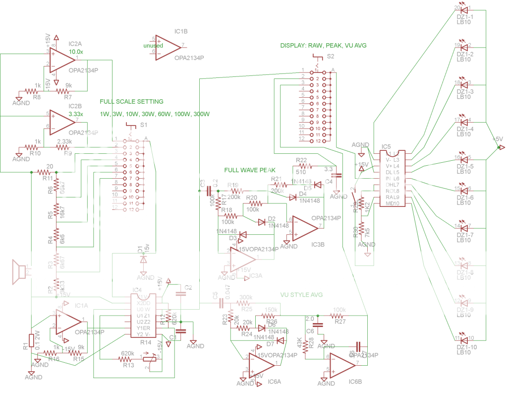
Okay, here is my latest version.
Its all pretty much from the AD734 and LM3916 datasheets.
IC1A is there to compensate for the .1ohm resistor - the voltage across it is too small for the multiplier to use accurately (I think). I've added precision full-wave peak detection and VU-style precision average detection between the multiplier and led driver chips.
I know its a bit messy, but I'd appreciate it if people would look over component values. I'd be glad to share the Eagle files. I think the schematic is getting pretty close.
One thing I was confused about - is a zener the wrong choice of diode for protecting they X input on the multiplier? Shouldn't I have used just a regular diode? I already switched out the zener, but let me know if I can use a zener, as it might be cheaper.
An externally hosted image should be here but it was not working when we last tested it.
Its all pretty much from the AD734 and LM3916 datasheets.
IC1A is there to compensate for the .1ohm resistor - the voltage across it is too small for the multiplier to use accurately (I think). I've added precision full-wave peak detection and VU-style precision average detection between the multiplier and led driver chips.
I know its a bit messy, but I'd appreciate it if people would look over component values. I'd be glad to share the Eagle files. I think the schematic is getting pretty close.
One thing I was confused about - is a zener the wrong choice of diode for protecting they X input on the multiplier? Shouldn't I have used just a regular diode? I already switched out the zener, but let me know if I can use a zener, as it might be cheaper.
The sound card trick could be used as a scope to verify no clipping. Calibrating the sound card as a power meter directly would be tedious but using an RMS voltmeter to read the voltage just before clipping should be quite accurate - assuming the meter is good. I use an old Fluke 8060A that is flat to 100 KHz and very good on accuracy.
If you go this route be very careful that you don't blow out the front end of the sound card. It would be VERY EASY to damage it if you're not careful.
G²
Yeah, I've blown a couple over the years. Sucks.
I'm not interested in clipping behavior, I'm trying to measure the power passing through a driver when listing to music.

Yeah, I've blown a couple over the years. Sucks.
I'm not interested in clipping behavior, I'm trying to measure the power passing through a driver when listing to music.
Power output when clipping is considered invalid as the distortion goes way up. Do you care about that?
G²
I don't think that the full wave rectifiers are necessary. Just a peak and an average. The multiplier output averages can only be positive.
It would be interesting to sense the voice coil temperature and loudspeaker diaphram excursion to know how close they are to destruction
Just for interest I have attached the schematic that I used but the differental amplifier could probably be replaced with an integrated solution and the multiplier is out of date.
Attachments
Hi,
The real question is what practical use is a real average wattmeter ?
(In this case for a variable impedance loudspeaker loads).
Answer - not much. You can't really use it for anything. So why build it ?
You can convert I and V to DC and multiply them but you won't get the real
average power dissipated in the load, you'll get the average VA of the load,
which due to phase angles is always more than the real watts, so it won't
be a real "wattmeter" either. If it had a practical purpose .....
rgds, sreten.
There are good reasons "real" wattmeters don't really exist .....
Last edited:
The averaged output of the analogue multiplier will be the real power dissipated in the loudspeaker mainly lost as heat in the voice coil. Not VA. With a completely reactive load with no real component the average output of the analogue multuiplier will be close to (ideally actually) zero.
Real Wattmeters exist for measuring 50 Hz power. A handheld unit from about 25 years ago used an analogue multiplier. I guess that these days they use Analog to Digital converters and a processor.
The proble with measuring the power dissipated in the load is that with a two or multiway speaker it isn't possible to know without using a Watt meter on each drive unit which voice coil is close to being toast and it doesn't measure how close you are to damaging the cone suspension or ABR!
It would be interesting to sense the voice coil temperature and loudspeaker diaphram excursion to know how close they are to destruction
We used to do that at KEF. Capacitor couple the drivers then inject a little DC current through the voice coil. Low pass filter the voltage across the VC and you are measuring DCR in real time. All you have to do is calibrate the meter for temp versus the percentage rise of resistance.
We would find that the temperature would hang around ambient most of the time and just rise off the peg for the loud sustained bits. But crank it up a few more dB and suddenly the temperature would take off.
Thats how voice coils get burned out. Trying to get it "a little louder" really ups the power absorbed.
David
We used to do that at KEF. Capacitor couple the drivers then inject a little DC current through the voice coil. Low pass filter the voltage across the VC and you are measuring DCR in real time. All you have to do is calibrate the meter for temp versus the percentage rise of resistance.
Thanks for the information. Testing AC mains transformers was similar but not real time measuring the resistance of the primary after a few hours running at maximum and comparing with the cold resistance to estimate temperature.
I remember assembling some Wilmslow Audio kits using a similar drive unit line up to the KEF 105 for a friend. The B300 bass units didn't last long! They were given some abuse though.
Thanks for the information. Testing AC mains transformers was similar but not real time measuring the resistance of the primary after a few hours running at maximum and comparing with the cold resistance to estimate temperature.
Yes, a transformer would retain its heat for possibly an hour. Voice coils have a short time constant and need to be measured real time. For the km1 I did many chart recorder tests to find the short term (voice coil) and long term (magnet structure) time constants so that we could model them for protection circuitry.
David S
- Status
- This old topic is closed. If you want to reopen this topic, contact a moderator using the "Report Post" button.
- Home
- Design & Build
- Equipment & Tools
- Okay, lets actually build a wattmeter