Yes. Try changing the 100k resistors around the opamps for 10k, or even less. That might be enough to get the bandwidth you need.PChi said:You have used rather high value resistors.
Hi thanks for the excellent links (still reading).
The problem was (still is) the resistor network I have used to divide the input signal by 10 or by 100. The resistors were closely placed together and it seems at higher frequencies the signal simply jumped from one to the next thus not being attenuated as it should. I replaced the resistors placing them wider apart and this made a big difference, but still is not perfect.
The problem was (still is) the resistor network I have used to divide the input signal by 10 or by 100. The resistors were closely placed together and it seems at higher frequencies the signal simply jumped from one to the next thus not being attenuated as it should. I replaced the resistors placing them wider apart and this made a big difference, but still is not perfect.
So I think that when I meantioned "floating voltages" some people instantly thought "many hundreds or thousands of volts in high tension photovoltaic circuits, or tube amplifiers" but I say again this is not the reason to try and do this.
Well, I mentioned the high voltage part for several reasons:
- it's one of the reasons to use diff probes;
- other people are going to read this thread too (now or in a couple of years);
- you may want to measure higher voltages at some point in the future.
BTW, 100 Vp can hardly be called low voltage (= 200 Vpp or 141 Vrms).
Hi thanks for the excellent links (still reading).
The problem was (still is) the resistor network I have used to divide the input signal by 10 or by 100. The resistors were closely placed together and it seems at higher frequencies the signal simply jumped from one to the next thus not being attenuated as it should. I replaced the resistors placing them wider apart and this made a big difference, but still is not perfect.
Google "diy differential probe". I did and I found some threads in another forum from which I get the impression that getting a flat frequency response of a diff probe is very difficult. Hence the high price. Perhaps you can find some tips'n'tricks there too.
"The resistors were closely placed together and it seems at higher frequencies the signal simply jumped from one to the next thus not being attenuated as it should."
Is this in a "breadboard" layout, with lots of stray wires? In any case you are suffering form feedback / oscillation which you will only resolve by looking at it with your 'scope!
This kind of gain / precision will only work with a pretty tight, clean layout and a ground plane. A prototype can get close if you use the "dead bug" method on some bare pcb board, grounded.
See around page 4
http://www.dartmouth.edu/~sullivan/prototyping.pdf
I take it all back. It is not the resistors proximity on my divider network or the breadboard itself.
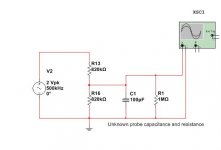
I just did a cold test, and was amazed at the results. I created a simple resistive divider with two resistors of 820K each, as shown in the attached picture. For 200Hz I read +/- 1V on the scope. At 200KHz I read +/- 0.8V and at 500KHz I read +/- 0.5V. Replacing the resistors on the divider with 10K values, and talking them completely out of the breadboard makes no difference.
I know the probe has a small capacitance but to be unable to read a 100KHz frequency from a simple resistive divider of 20K is news to me. I cannot simulate this on my simulator, any value of parallel capacitance that I add works only for a single value of resistors on the potential divider, whereas the scope produces consistently incorrect results regardless of the values of the resistors.
Edit: the capacitor and 1M resistor were not on the test circuit, I have added them to the simulation to try and recreate the phenomenon.
Attachments
Last edited:
AKIS, you really must slow down and be more methodical.
1) always check things at DC first. That eliminates C, L and checks that resistor ratios are as you expect.
2) 100pF at 100Khz is Z=16K! Completely KILLING your divider. Do your sums first!
For a 1% error, any loading must be >100 times the source. So with 20K resistors you will need in the order of >2M load
3) Do it at DC FIRST! (Did I already say that?)")
1) always check things at DC first. That eliminates C, L and checks that resistor ratios are as you expect.
2) 100pF at 100Khz is Z=16K! Completely KILLING your divider. Do your sums first!
For a 1% error, any loading must be >100 times the source. So with 20K resistors you will need in the order of >2M load
3) Do it at DC FIRST! (Did I already say that?)
Last edited:
The picture above is a simulation trying to recreate the error that I got by testing - I added the cap and resistor to reproduce the error in simulation.
There must be something wrong with my oscilloscope/probes or I am missing something. My scope is rated 20MHz.
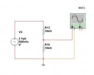
Here is another picture of the *real* test I did. If you have an oscilloscope handy can you please tell me what it reads? It should read +/- 1 V. But I read 0.5V at 500KHz and 0.8V at 200KHz.
There must be something wrong with my oscilloscope/probes or I am missing something. My scope is rated 20MHz.
Here is another picture of the *real* test I did. If you have an oscilloscope handy can you please tell me what it reads? It should read +/- 1 V. But I read 0.5V at 500KHz and 0.8V at 200KHz.
Attachments
Yes, do the sums first. I know that approach can be unpopular around here, but it does save a lot of wasted time and confusion. If you can't calculate it then you aren't designing it.
What scope probes are you using? I assume you do know about cable capacitance and 10:1 probes etc? Having a scope which goes up to 20MHz is no use with high capacitance probes and a high impedance circuit.
What scope probes are you using? I assume you do know about cable capacitance and 10:1 probes etc? Having a scope which goes up to 20MHz is no use with high capacitance probes and a high impedance circuit.
Last edited:
In theory it should be what you calculate, of course.
Since no-on else has your 'scope it is pointless trying to duplicate your results.
More questions, which, if you ignore, I shall respectfully bow out! We ARE trying to help ...
1) What is the published spec of your scope / probe input? Z, C
2) If x1, it will have a high(ish) C.
3) If x10 it will be useless at >> DC unless it is calibrated with a square wave input.
4) Humour me and calculate (approx fag-packet will be fine), what value of C across the lower R will give the result you get, assuming everything else is perfect.
Does that value of C relate to the environment / errors you are seeing?
(Clue: 30pF at 500Khz ~ 10K)
Cliff
OK, I read a bit more about my scope (but still not done). The scope is Beckman Industrial 9020. It says input impedance 1M and 35pF. I am not sure whether the probes were originals, I kind of think they were, but it's been a long time. I must have bought the scope of a bulletin board probably before ebay. It is so old I cannot remember when I bought it.
The cap needed to drop the voltage from 1V to 0.5V at 500KHz on a 10K+10K divider is 110pF.
I have just experimented a bit more and used the tiny screw on the probes. On the X1 position on the probe the screw makes very little difference, and it still produces wide errors. But on the X10 position it has a big effect and actually I managed to "calibrate" the probes to read the correct voltage at 500KHz - but only on the X10 setting.
Which means I must leave the probes on the X10 setting from now on, and read more to understand the differences between X1 and X10.
The trimmer capacitor on the probe should make no difference on x1, but correct setting is crucial on x10. Most scopes have a front panel square wave for setting the probe trimmer. Once set leave it alone.
110pF is easily possible from probe cable capacitance. You won't be able to measure 500kHz on x1 except on a very low impedance circuit.
Once you get your scope probes sorted, you may then find the sort of problems with stray capacitance in your circuit which we thought you had before.
110pF is easily possible from probe cable capacitance. You won't be able to measure 500kHz on x1 except on a very low impedance circuit.
Once you get your scope probes sorted, you may then find the sort of problems with stray capacitance in your circuit which we thought you had before.
Good!
There is plenty of stuff on the web about probes, impedance and compensation.
Look for the difference between a x1 and x10 input.
BTW are you sure about your C calculation? I did it "rule-of-thumb" and got less, but I may be wrong. I hate sums.
Lesson learned, hopefully for lifeD) NEVER believe what a test instrument tells you until you are sure it is reasonable. Then check it again.
I learned this the hard way, but it was 45 years ago!
Cliff
There is plenty of stuff on the web about probes, impedance and compensation.
Look for the difference between a x1 and x10 input.
BTW are you sure about your C calculation? I did it "rule-of-thumb" and got less, but I may be wrong. I hate sums.
Lesson learned, hopefully for life
D) NEVER believe what a test instrument tells you until you are sure it is reasonable. Then check it again.I learned this the hard way, but it was 45 years ago!
Cliff
The trimmer capacitor on the probe should make no difference on x1, but correct setting is crucial on x10. Most scopes have a front panel square wave for setting the probe trimmer. Once set leave it alone.
110pF is easily possible from probe cable capacitance. You won't be able to measure 500kHz on x1 except on a very low impedance circuit.
Once you get your scope probes sorted, you may then find the sort of problems with stray capacitance in your circuit which we thought you had before.
Yes I also have the square wave but it looked perfect on the X1 setting. Of course I have just read on the manual (which I have just downloaded for first time) that it always looks good on the X1...
I thought the X1 - X10 was simply a convenience thing, ie if you are measuring large voltages use the X10 else use the X1. I had no idea that frequency and circuit impedance also plays a part. As the scope is 20MHz, I had thought that 500KHz is peanuts and does not require extra consideration.
Tomorrow I will try the differential amp again and make better measurements to see what is really happening (hopefully).
Akis
You may have a look on this one.
http://www.diyaudio.com/forums/equipment-tools/189545-implementing-y-out-oscilloscope-8.html#post2622342
It works for me.
Check out the IC datasheet to see if it is OK for your requirements
George
Now that I have read a bit more and understand the issue a bit better.
I need a device to put between the oscilloscope probe and the component under measurement so as to isolate the component from the probe's earth lead and so be able to make floating voltage measurements.
Because the device will be battery operated we need to reject voltages many times the supply rails. If the device is not battery operated then it is not very portable, but in any case even the max 30-40V DC on an op-amp is not good enough range.
In addition the device must not load the circuit with low impedance and/or high capacitance. So we are looking for 1M-10M impedance and a tiny capacitance if possible.
So this is what I am working on now. First I will try a two chip classic difference amplifier where the first stage does a 10:1 signal conversion (therefore allowing large common voltages to be present) and the second stage recovers the loss. I will see how that performs at 500 KHz.
Then I will try a variation of the classic 3-op-amp in-amp circuit, but with a change so that it also performs a 10:1 reduction at the inputs.
Once I get something working for real (not just on the simulator) I will post it here.
- Status
- This old topic is closed. If you want to reopen this topic, contact a moderator using the "Report Post" button.
- Home
- Design & Build
- Equipment & Tools
- Measuring floating voltages with oscilloscope