Tektonix make it very clear that disconnecting the PE/earth connection of the scope is potentially very dangerous.
What about floating the DUT with the scope properly earthed?
floating measurements have been made by knowingly defeating the built-in safety ground features of oscilloscopes or measurement instruments in various manners. THIS IS AN UNSAFE AND DANGEROUS PRACTICE AND SHOULD NEVER BE DONE!
What about floating the DUT with the scope properly earthed?
Last edited:
It is threads like this which are good arguments for a newbie-tag: I can't measure 500kHz with a 20MHz scope (but by the way I haven't yet read the manual so I don't know how 10:1 probes work, but I can't tell you that because I don't know that I don't know it).
 ^n
^n70Vac ~= 100Vpk = 200Vpp................100 Vp ....... (= 200 Vpp or 141 Vrms).
Tektonix make it very clear that disconnecting the PE/earth connection of the scope is potentially very dangerous.[/COLOR]
What about floating the DUT with the scope properly earthed?
It is not that simple (for me).
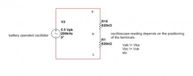
Here is a most basic experiment. The oscillator is battery powered. On the attached schematic you'd think that the voltage between a-b and b-c would be equal and half of the total voltage, that across a-c.
The scope does not measure half because it has a capacitance and a resistance, so we expect a bit less than half.
However how can we explain that the scope measures Vab to be wildly different to Vba (ie turn the terminals around) ? Similarly Vbc is wildly different to Vcb. The correct reading (something a bit less than half voltage) is taken in a particular direction only.
I cannot explain this, and at the risk of being called a complete newbie, I am asking here.
Attachments
Probably because it really isn't floating? (at 500Khz)
Much lower impedance to ground at one end (ground as in what the scope is connected to.)
Why are you making life so difficult for yourself, AKIS?
Trying to measure voltage with source impedances about 1MR is FRAUGHT with difficulties, even if you really understand your test equipment and measurement
techniques.
Try it with 1K resistors. If you get the right answers your problem is as above.
Nothing working at AC much above audio frequencies is 'floating', because of stray capacitance. Welcome to the world of RF! Nothing is exactly as it appears on the circuit diagram.
Please don't be offended by me implying that you are a newbie. This is simply a statement of fact, and may help people give you more appropriate advice.
Please don't be offended by me implying that you are a newbie. This is simply a statement of fact, and may help people give you more appropriate advice.
I am examining this because the differential circuit was going to have such a resistive network at its front end.
There may be something wrong with my scope / probes. I will buy a new scope anyway. In the meantime if anyone would like to try that little test above, I would be grateful to know if you are also getting weird readings when you turn the terminals over. By "weird" I mean reading just 5% of the voltage when you reverse the terminals.
There may be something wrong with my scope / probes. I will buy a new scope anyway. In the meantime if anyone would like to try that little test above, I would be grateful to know if you are also getting weird readings when you turn the terminals over. By "weird" I mean reading just 5% of the voltage when you reverse the terminals.
Checkout the OPA117 by Burr Brown. A differential amp with a gain of one, 300V common mode range on the input when used with +/- 15V rails. Not totally isolated but fairly high impedance.
Never float the ground on your scope!
OOPs! That should have been INA117P. TI now owns Burr Brown. I was just going from memory. Common mode range on the input is just +/- 200V. If the input impedance is too low, use a differential opamp buffer operating off of floating power supplys (or batteries. Then use the INA117 to sum the outputs and reference the output to ground.
Here's the marketing blurb: Amplifiers and Linear - Difference Amplifier - INA117 - TI.com
Here's the data sheet: http://www.ti.com/lit/ds/symlink/ina117.pdf
My money is on 'operator error', which includes misinterpreting results, ignoring parasitic components, and using unofficial 'grounds' (including the operator's body). We have tried to explain what is happening, but you seem to desire a more esoteric explanation.
Agreed, I have seen all sorts of unexpected things with probes held on traces.
Even though I don't deal that much with scopes, I do know that measuring with it (1:1, 10:1) in high impedance circuits is like asking for trouble. Not all oscillators like the load of the probe (incl. its capacitance) and stop working the moment you touch one of its leads. Tracing an error on a board that's not working you're falsely led into believing the oscillator doesn't work...
Measuring for oscillating circuits, the extra capacitance might actually help in stopping it (or the reverse) temporarily...
Quite often boards that refuse to be programmed can be "helped" by putting a probe on the relevant trace. Putting the probe on the trace creates a situation in which programming is possible (after which the boards keep working without the probe because the programme is in it).
Then there's blowing up components by connecting scope ground to a ground in the circuit that is actually 300 V above earth potential...

Last edited:
Yes the device under test was floated by using a battery to power it, so no relationship to earth at all.
I have done more thinking and taken measurements.
As you have said, trying to measure at high source resistances is asking for trouble.
I calibrated the probes in the 10X setting using a square pulse. I found that the calibration is different at 10KHz than at 1KHz. I settled with 10KHz calibration.
Then the channels A and B must be adjusted so that in differential mode (ADD) the sum is 0 for the same source signal at the highest sensitivity (eg 5mV per division). If you do not do that then you will read different values when you reverse the probes. This answers one of my questions.
Still there are readings I do not easily understand. I have taken them all down and will have to study more in case I discover some pattern or explanation.
On another board someone mentioned "self capacitance" but I did not really get it.
The outcome of all this is the confidence in one's instruments and measurements.
I have so far learned how to adjust the scope, how to be very suspicious of its capacitances and how 200KHz is not a trivial frequency.
I think paying 300 pounds for a differential probe which is guaranteed to work is probably worth it
No. All RF circuits have a relationship to earth via capacitance.akis said:Yes the device under test was floated by using a battery to power it, so no relationship to earth at all.
Self capacitance can seem a bit strange to people who think of a capacitor as a two-terminal component. Self capacitance is like a capacitor with only one terminal - the rest of the entire universe forms the other terminal. It can be a significant issue in high impedance RF circuits. Every node in the circuit will have some self capacitance.
Some progress, AKIS! Good!
BUT, since the source is fully floating why not simply ground (scope gnd) one output terminal and remove all need for differential measurements?
Please explain why you think this is not appropriate.!
Cliff
Hi, yes just that. Since the oscillator is truly floating, to the best of my abilities, I figured it would not make any/much difference if I earth its common, or its output pin. However this is far from true, and not intuitive at all. It is part of the "mystery". I did not have time to think about it more, and that's why I did not reply earlier, nevertheless, if one side of the circuit has just 2pF more earth capacitance than another, then at 200KHz 2pF is 400K Ohm, and that would account for the "weird" results. Part of that was observed, I think, when I powered the circuit with two 9V batteries, and then realised that in some measurement modes, where I did not ground the "common", touching the battery cases surely made a huge difference.
If I ever manage to put all this into the simulator and receive similar readings I will post here. Basically a model of the two batteries, oscillator and probe - so that the simulator reads more or less what I read in practice.
LTspice does have a stray capacitance option from every node to its reference node (0), and I always use it. Stray conductance is there as well. Of course it's only lumped element stuff, no wave propagation involved.Do simulators include stray capacitance to the rest of the universe? I suspect not.
- Status
- This old topic is closed. If you want to reopen this topic, contact a moderator using the "Report Post" button.
- Home
- Design & Build
- Equipment & Tools
- Measuring floating voltages with oscilloscope