Is it possible to use a DSO by any means to figure out the timing quality of a digital stream ? Say for example spdif digital ouput. Is there any way you could use a DSO to get an idea of the frequency stability/quality(jitter, wander etc).. of a spdif stream coming out of a source ? If so can anyone please explain how ?
Thanks!
Thanks!
Here is a place to start -- Eye pattern - Wikipedia, the free encyclopedia
Thanks. But I didn’t get the trigger part. What would be used as the trigger ? the data signal itself ? or an accurate clock running at the same speed as the data rate of the stream ? because its only the raw spdif data at that point and no clock is available. This is for the spdif data coming out of the source prior to getting fed into a spdif receiver.
Unfortunatly DSO can't be directly use to make jitter measurement on SPDIF stream because DSO triggering have also it's own jitter and often more than what you want measure. Altrought it's possible to do measurement if jitter is high and if you scope is good.
Jitter is generally measured with spectrum analyser or with specific instrument that can measure each period of the stream and perform an histogram dsiplay off accumated values.That allow showing if jitter noise is random or corralated of a noise source.
Frex
Jitter is generally measured with spectrum analyser or with specific instrument that can measure each period of the stream and perform an histogram dsiplay off accumated values.That allow showing if jitter noise is random or corralated of a noise source.
Frex
I agree with Frex, to the degree that inexpensive, and most any USB based DSO, will suffer from the irregular triggering he describes--this is not so for the better DSOs, even older units like Lecroy's 93xx and 94xx instruments.
Here is a capture of the jitter in a 990kHz square wave generated by an inexpensive FPGA based DDS function generator, being pushed to its limits, and being asked to generate an output signal that is not an even multiple of the device's 50MHz clock frequency:
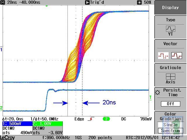
The upper trace is the square wave output, the lower trace is the generator's trigger output--this is being used to trigger the scope, a Lecroy waveJet 322.
Note that the jitter spans 20ns, not the least bit coincidental to the function generator's 50MHz master clock and the result of the FPGA only being capable of doing one thing at a time. Many USB scopes are also FPGA based and suffer from this same issue in both triggering and simultaneous sampling of both channels.
With access to the clock signal used to create the S/PDIF stream this same exercise could be performed...
Here is a capture of the jitter in a 990kHz square wave generated by an inexpensive FPGA based DDS function generator, being pushed to its limits, and being asked to generate an output signal that is not an even multiple of the device's 50MHz clock frequency:
The upper trace is the square wave output, the lower trace is the generator's trigger output--this is being used to trigger the scope, a Lecroy waveJet 322.
Note that the jitter spans 20ns, not the least bit coincidental to the function generator's 50MHz master clock and the result of the FPGA only being capable of doing one thing at a time. Many USB scopes are also FPGA based and suffer from this same issue in both triggering and simultaneous sampling of both channels.
With access to the clock signal used to create the S/PDIF stream this same exercise could be performed...
I agree you need an advanced scope to do this to any precision, i.e. 500MHz BW or greater, 2GS/s sample rate or better. I made and wrote about these measurements in 1996 for an Audio Electronics article called Jitter RIP Part II. For that article, I used both a scope and dedicated HP E1725A Time Interval Analyzer. These days you can buy special software that analyzes a buffer of scope captured data, and gives you similar jitter measurements.
There is a repetitive aspect to SPDIF, if you can figure out how to trigger on it, (many scopes have very advanced triggering) you can measure the pk-pk jitter as above. A more reliable way is to use a receiver that generates a clock directly from the SPDIF stream, such as the CS8412. On that one, the L/R clock is derived directly from the SPDIF embedded clock. If you measure that , you can easily measure the inherent jitter or the source clock and SPDIF stream (albeit also the receive side too). But that method was extremely informative in showing how SPDIF jitter correlated to the source transport, cable, and also SPDIF transmit electronics, plus correlation to SPDIF signal rise times, etc.
There is a repetitive aspect to SPDIF, if you can figure out how to trigger on it, (many scopes have very advanced triggering) you can measure the pk-pk jitter as above. A more reliable way is to use a receiver that generates a clock directly from the SPDIF stream, such as the CS8412. On that one, the L/R clock is derived directly from the SPDIF embedded clock. If you measure that , you can easily measure the inherent jitter or the source clock and SPDIF stream (albeit also the receive side too). But that method was extremely informative in showing how SPDIF jitter correlated to the source transport, cable, and also SPDIF transmit electronics, plus correlation to SPDIF signal rise times, etc.
Last edited:
I am doing exactly this kind of testing since 2010. I have shown the first results on this forum here:
http://www.diyaudio.com/forums/digi...tenuators-jitter-reducers-30.html#post2352977
The more detailed description here:
http://www.diyaudio.com/forums/digi...tenuators-jitter-reducers-31.html#post2353193
A long thread and lots of measurements of this kind here:
DIYHiFi.org • View topic - Some jitter analysis - and beating of a dead horse..
Ciao, George
I am doing exactly this kind of testing since 2010.
A long thread and lots of measurements of this kind here:
DIYHiFi.org • View topic - Some jitter analysis - and beating of a dead horse..
Ciao, George
Yes, exactly how one triggers directly on the SPDIF stream to measure the jitter - great job! - from that thread
"The lower, pink trace is the physical scope trace, the classic SPDIF signal. To get the less noise possible, I'm churning up the channel gain. For the TIE reconstruction only the edges are needed, anyway.
I'm triggering on the "B" type preamble, which starts the (SPDIF) data blocks / data words. The "W" type preamble is also shown, a bit more asymmetric. It starts the second channel data."
If you have a delay triggering function in the scope, you can trigger it on point X, but see a point X+t on the screen, where t is trigger delay.
Then you won't see sample-sample jitter, but accumulated jitter between point X and X+t.
This method emphasizes the jitter view of waveform on low frequencies.
Then you won't see sample-sample jitter, but accumulated jitter between point X and X+t.
This method emphasizes the jitter view of waveform on low frequencies.
If you have a delay triggering function in the scope, you can trigger it on point X, but see a point X+t on the screen, where t is trigger delay.
Then you won't see sample-sample jitter, but accumulated jitter between point X and X+t.
This method emphasizes the jitter view of waveform on low frequencies.
That's a great technique, and then use peak hold display to build the envelope. Using an HP 2GS scope, I was able to easily see 100ps peak-peak of jitter envelope. This equates to about 16 ps rms, using the divide by 6 rule of thumb (for random jitter, converting peak to peak to rms).
There is also a company that makes jitter analysis software, Amherst Systems Associates or ASA. The software works with most decent scopes, but starts in the $2K range.
If you have a delay triggering function in the scope, you can trigger it on point X, but see a point X+t on the screen, where t is trigger delay.
Yes, it's a good method -but it needs a really good scope. Because it adds up not only the scope trigger jitter but also the delay generator's intrinsic instability. If memory does not cheat me, (it was '98!) I remember of something like 50psec p-p either on a TDS654C or on a 2465B! (yes, it's also possible on a good analog scope, though one can not see all full 6sigma coverage..)
I have used a good oscillator, so it was for sure way below of this level in reality.
Ciao, George
- Status
- This old topic is closed. If you want to reopen this topic, contact a moderator using the "Report Post" button.
- Home
- Design & Build
- Equipment & Tools
- Can a DSO be used to test riming quality of a digital data stream ?