Very informative link. I was just looking over some linear output optic isolators. Maybe its as simple as scaling your sense resistor so at max current the led is at max brightness.
If you want to measure current on the low side, ST makes some nice little fixed gain opamps for sense resistors. See the TSC101.
A wise man once told me "Design around Digikey. Otherwise you'll design around this awesome part that you can't buy because nobody stocks it."
If you want to measure current on the low side, ST makes some nice little fixed gain opamps for sense resistors. See the TSC101.
A wise man once told me "Design around Digikey. Otherwise you'll design around this awesome part that you can't buy because nobody stocks it."
Wouldn't it be a lot simpler to just put one opto set in the serial USB link?
I guess there was (is?) some backward compatibility issue with analog impedance on the USB line, but can't that be dispensed with now?
The USB link has power and ground so it isn't easy to isolate.
One would think that someone would have come out with an IC interface for USB that performs the isolation functions by now, could just go serial USB to serial port or parallel port.
The Xantrex power supplies I have use two uP's with optos (serial port) between them to do the isolation functions for digital PC control. An internal floating supply powers the outboard oriented uP. An XHR-600 off Ebay gives you floating 0-600V for plate supply with PC control and current and voltage readbacks (16 bit A/D and D/A). An XT-250 gives 0-250V for screen supply with the same features. You can run the whole show from the PC using the readbacks.
The Xantrex power supplies I have use two uP's with optos (serial port) between them to do the isolation functions for digital PC control. An internal floating supply powers the outboard oriented uP. An XHR-600 off Ebay gives you floating 0-600V for plate supply with PC control and current and voltage readbacks (16 bit A/D and D/A). An XT-250 gives 0-250V for screen supply with the same features. You can run the whole show from the PC using the readbacks.
Last edited:
One would think that someone would have come out with an IC interface for USB that performs the isolation functions by now, could just go serial USB to serial port or parallel port.
The Xantrex power supplies I have use two uP's with optos (serial port) between them to do the isolation functions for digital PC control. An internal floating supply powers the outboard oriented uP. An XHR-600 off Ebay gives you floating 0-600V for plate supply with PC control and current and voltage readbacks (16 bit A/D and D/A). An XT-250 gives 0-250V for screen supply with the same features. You can run the whole show from the PC using the readbacks.
There are isolated USB and RS232's -- I used some from Maxim about 10 years ago. There are also ADC/DAC cards which are isolated. It gets expensive, however.
At any rate, it's very important to keep the two sides separate since power supplies can issues.
The Application Note from Vishay appears to be updated from the version which I have -- see figures 8 and 10.
http://www.vishay.com/docs/83708/appn50.pdf
The material is equally applicable to the HCNR200 -- there's a spice model for this part on the Avago datasheet (Avago Technologies Semiconductors Analog, Mixed-signal and Optoelectronic Components and Subsystems) -- used to be Hewlett Packard's semi biz.
Right, a high side servo with opamp powered off the high side. Not particularly simple. They illustrate isolating 2 electrical domains that each already have VCC and ground. Devising a floating high side power supply that doesn't influence the measurement is I think a bit of a challenge. Still might be worth playing it out though...
There are isolated USB and RS232's -- I used some from Maxim about 10 years ago. There are also ADC/DAC cards which are isolated. It gets expensive, however.
At any rate, it's very important to keep the two sides separate since power supplies can issues.
I think there are 2 distinct issues here; one is the possibility of the computer interface being energized through some colossal failure inside the tracer. The other is how to do current measurement safely.
Implementing isolated high side current measurement seems nice, but doesn't completely eliminate the HV risk.
Twisted pair Ethernet is balanced and transformer isolated.
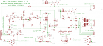
Here is an iteration of the regulator using transformer isolation of the current measurement, plus current limiting and voltage readback. I think there is still an issue of C2 and C3 needing to be scaled for the measurement current.
Attachments
USB Isolator
Analog makes a dedicated USB isolator chip ADUM4160 | Full/Low Speed USB Digital Isolator | Digital Isolators | Interface | Analog Devices
Analog makes a dedicated USB isolator chip ADUM4160 | Full/Low Speed USB Digital Isolator | Digital Isolators | Interface | Analog Devices
The USB link has power and ground so it isn't easy to isolate.
Use an isolated power supply for the USB interface.. If you are using opto of magneto isolation for data, you don't need the ground.
Please pardon me for butting in, here, but...
Some of you guys are getting down into the weeds way too fast.
(...)
You will consider alternatives based on some of the details of how they might be implemented as circuits, before that, of course, but even at that point you're still not ready to go as deep as where you're trying to already jump to.
Doing things properly, in sequence, and spending more time planning at the beginning, can definitely save both time and money, and should get the best end result.
Maybe the first thing for everyone to come to terms with is: Whose thread is this and what is its purpose?
Michael Koster is the thread starter. So he can decide that, if he wishes. And he does seem to already have some things planned and some implementation details more-or-less decided.
So if there are others who would like to start back at the initial planning stage, it wouldn't hurt to start a different thread. It would probably be beneficial to both.
Thanks for the reality check. I haven't done a thorough job of revealing my process, sort of jumped in to the middle. I will document the backstory a little better over time.
My functional specification was arrived at by thinking about my needs and the needs of the current vacuum tube world. It would be helpful if I were to post it here but I don't think there's anything controversial.
I also have gone through a series of high level design iterations where I thought about trying to synthesize ramps, etc. which is wasteful and complex, etc., eventually settling on the pulse technique using programmable regulators.
The Arduino while not ideal for it's lack of D/A outputs still is the obvious choice for it's open HW and open SW platform support. I've built enough stuff with Arduino to be learning it's limitations and I see no show stoppers.
I have a simple block diagram which I will post when I get it bitmapped somehow but it's basically the Arduino, a D/A converter, and the regulators doing the work. I posted the regulator schematic in progress because it shows a fairly revealing slice of the system.
I also have some flowcharts I've been working on showing the measurement cycle for plate curve generation. There is also some detail worked out about the PC interface handshake. As I mentioned earlier, my first goal is simply to run plate curves from start-stop-step parameters and chunk out CSV data to the PC where it's going to be loaded into excel for plotting. I'm confident that any more sophisticated stuff can be built on the basic platform.
Also I am approaching this design in a nontradional way. Rather than enforcing a strict modular partitioned top down design process, I'm expecting to continue to iterate as this progresses. Everything is a prototype. It's called "protovation" and the basic idea is to find a good starting point and innovate through prototyping. It's pretty much the polar opposite of a NASA moon shot

The thing I need to get better at is the communicating the high level intentions and process so others can understand and possibly participate.
Cheers,
Michael
Last edited:
...snip...
An XHR-600 off Ebay gives you floating 0-600V for plate supply with PC control and current and voltage readbacks (16 bit A/D and D/A). An XT-250 gives 0-250V for screen supply with the same features. {/QUOTE]
The last one on ebay sold for over $1000. I think they will not be a good option.
Whatever is designed, should be built from scratch wherever possible to keep cost down.
I got mine a few years ago when some semiconductor line got scrapped. Could get "not working" ones for $50. All turned out to be easy to fix. And working ones for $300. I agree though that these are not suitable currently.
The USB chip isolator looks interesting. Does Ethernet have a sufficient common mode voltage rating? I know modem cards go pretty quick if there's lightning storms around. I put big common mode chokes on the tele. lines to protect them.
The USB chip isolator looks interesting. Does Ethernet have a sufficient common mode voltage rating? I know modem cards go pretty quick if there's lightning storms around. I put big common mode chokes on the tele. lines to protect them.
QGS reveals:
TP ethernet transformers are tiny, but the nominal insulation rating is typically 1500V. They are tested at 500V, 1KV, and 1.5KV DC, also with 120VRMS.
Is galvanic isolation of the computer-to-microcontroller interface really a requirement for safety in this case?
BTW, I don't know how this whole thing became an isolation problem Can we talk about testing tubes?
TP ethernet transformers are tiny, but the nominal insulation rating is typically 1500V. They are tested at 500V, 1KV, and 1.5KV DC, also with 120VRMS.
Is galvanic isolation of the computer-to-microcontroller interface really a requirement for safety in this case?
BTW, I don't know how this whole thing became an isolation problem
Can we talk about testing tubes?
Last edited:
Someone is worried about blowing up a PC under fault conditions.
Personally, I believe this is overly pessimistic. (unless I'm the one to have the PC blow up)
We can either talk about bits and pieces, or wait until you have the Block Diagram and System Specification available.
Personally, I believe this is overly pessimistic. (unless I'm the one to have the PC blow up)
We can either talk about bits and pieces, or wait until you have the Block Diagram and System Specification available.
If the plate voltage is going to be pulsed on, I assume the screen voltage will also. Leaving the screen V on would make some fireworks. Is the grid 1 voltage supply going to be + and - capable?
Something odd I have seen using a Tek curve tracer with some pentode tubes is hysteresis in the curves around the knees. At first I thought this was something to do with the tracer, but it was specific to certain tubes. It shows up in the plate curves as different knees when traced with increasing plate V and decreasing plate V. (which the Tek tracer does on alternate curves) This could be something useful to check for. But you won't see this with pulsed measurements.
By the way, the typical common mode voltage rating for commercial power supplies is only around 400 to 500 V typically.
Last edited:
Someone is worried about blowing up a PC under fault conditions.
Personally, I believe this is overly pessimistic. (unless I'm the one to have the PC blow up)
We can either talk about bits and pieces, or wait until you have the Block Diagram and System Specification available.
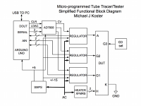
Here's the simplified block diagram.
All electrodes will be energized together using the LDAC signal. The CLR signal can be used to de-energize (restore to baseline voltages). The G2 and Anode regulators have a baseline voltage of zero and the G1 regulator has a range of -200 to +100 on the high range, and -20 to +10 on the low range. The raw supplies will be +/- 200V for G1 and +300 or +600 for G2 and Anode depending on the rectifier configuration.
Hysteresis and small signal gain can be tested using small steps as a separate measurement.
Attachments
It sounds like you are considering measuring Gm or Mu under user specified conditions. Nice.
It would be trivial to hold constant plate voltage and change the grid voltage in small steps for a direct gm measurement. Likewise the plate voltage can be adjusted to maintain current for a mu measurement. Holding grid voltage constant and varying plate voltage in small steps gives a direct Rp measurement.
Have You guys seen this DIY Computer tube tester / tracer machine:
Röhrenprüfgerät Röhrenmessgerät RoeTest
RoeTest - Computer Röhrenmessgerät /Röhrenprüfgerät - YouTube
Seems exactly what You want to achieve.
However, site is in German only.
P.S.:
I`m not related in any way with the guy who made this incredible impressive machine happen.
Röhrenprüfgerät Röhrenmessgerät RoeTest
RoeTest - Computer Röhrenmessgerät /Röhrenprüfgerät - YouTube
Seems exactly what You want to achieve.
However, site is in German only.
P.S.:
I`m not related in any way with the guy who made this incredible impressive machine happen.
- Status
- Not open for further replies.
- Home
- Design & Build
- Equipment & Tools
- A micro-programmable tube tracer/tester