You might be able to use 2 AD873's as a solution. Or Davida's ADC+DAC which is quite original and simple.
Or an OPA615 which has a BW into the MHz.
I recently breadboarded the sample & hold described in this project with a view to replacing the full wave detector in an oscillator I built a while back.
The existing detector has a small amount of ripple that contributes to the harmonic distortion. Attempts to increase the time constant makes the settling time too long and can result in squegging.
The oscillator in the original project write up only operates up to 10kHz. My oscillator covers 15Hz->150kHz in 4 switched ranges.
My tests show that the S&H works up to about 28kHz.
Above that, the sampling pulses stop.
For operation at higher frequencies, C9 and C10 need to be reduced to give narrower sampling pulses.
However, this stops it working correctly at lower frequencies.
The only answer I could come up with is to switch C9 and C10 according to the frequency range.
I tried using a 4066 analogue switch to do this.
It meant reducing the +/- 12V supplies on the S&H down to +/-9v.
I was also concerned about the spikes on the input to pin 6 of the comparator.
These exceed Vcc which could damage a 4066. It needs an added protection diode between pin 6 and Vcc.
I found that using values of 1nF for C9 and 56pF for C10, the S&H can be made to operate up to about 100kHz.
Above that, the delay in the sampling pulses relative to the peak of the sinewave cause the the AGC control output to drop.
Replacing the LED 'D3' with three diodes in series helps by widening the clipped top of the sinewave. However, this reduces the AGC output voltage somewhat.
Another problem with the S&H is the unwanted offset in the AGC control output due to the FET biasing resistor R15. This is easily corrected by replacing the FET with a voltage follower using the unused half of the second TL072.
I've now done a bit more work on the S&H and managed to get it to work up to 150kHz:-
I discovered I could make it work at low frequencies even when using the narrower 1usec sampling pulse. That meant I no longer need to range switch C10 or C9.
There was one problem that took me a while to figure out:-
The TL072 voltage follower I used to replace the FET Q1 appears to have problems driving the hold capacitor C11 at frequencies above 100kHz. A negative glitch appears on it's output coincident with the negative going edge of sampling pulse (i.e. track->hold). This spike only appears when the oscillator frequency is approaching 150kHz. Removing the protection diode I added to U3B pin 6 reduced the spike amplitude suggesting it might be feedthrough from the supplies. However, extra supply decoupling made no difference. Adding an emitter follower to the TL072 output fixed the problem. I am still unsure of the root cause.
While investigating the glitch, I tried using a 4098 monostable to generate the 1usec sampling pulses in place of the comparator, thinking that it might reduce the spikes on the supply. However, it did not help the glitch problem described above.
Another thing I tried was replacing the sampling FET Q2 with a 4066 analogue switch. That seems to work ok and reduces the sampling pulse feedthrough onto the AGC line.
All this experimentation is being carried out on a separate breadboad connected to the output of the existing oscillator. I have yet to accurately measure the AGC signal against the level of the sine wave input. If that looks ok, then I can think about replacing the existing full wave detector.
You are probably running into current limiting in the TL072. The datasheet suggests 1.2 mA is what you can expect without actually specifying.
The OPA2134 is good for 40 mA (on paper) There is a chart in the datasheet for overshoot vs. load capacitance and another for settling time. It may be a direct fit with much better accuracy. Not as cheap.
The OPA2134 is good for 40 mA (on paper) There is a chart in the datasheet for overshoot vs. load capacitance and another for settling time. It may be a direct fit with much better accuracy. Not as cheap.
You're seeing the charge injection from jfet Switch. You can compensate for the q injection. See the manual for the AP AP1. You can down load it for free from Ap's web site.
I'm no S&H expert, but I did read up about charge injection. I am not convinced this is the problem however...
Firstly, the problem only appears when the oscillator frequency approaches 150kHz. If it was a charge injection issue, then I would expect to see it at all frequencies.
Secondly, the amplitude of the glitch is considerably higher than I would have expected if it were down to charge injection.
Thirdly, I would not expect the amplitude of the glitch to be affected by either removal of the protection diode or by adding an emitter follower to the output of the voltage follower.
I think 1audio's suggestion that current limiting in the TL072 is more likely to be the problem - although it does seem odd that the glitch occurs on the falling edge of the sample pulse when the voltage follower is disconnected from the sampling capacitor.
I did try adding a high slew rate NE531 to the output of the TL072. (I know it's an ancient device, but I had some in my junk box). That did not help.
I will investigate the OPA2134.
The glitch does not actually appear on the AGC signal because it happens after the sampling pulse has switched off , so I could just ignore it. It is just something unexpected that doesn't look quite right.

Wayne,
Take a page from Richards book and stick it in a mini metal garbage/trash can.
Richard, didn't you mention that that worked for you? I think you even poasted
some pics of it but don't know how to find it them.
Signed
-- The Boss
Cheers
yes, a small all steel trash can with steel lid. Put the osc and its battery power supply inside and floating from can by wood blocks. Isolated feed-thru connector on can side to access the gen output. can grounded/earth.
But for the finished product, no such shielding is needed. Just care in test/usage setup grounding. No loops.
-Richard
I tried the idea of filtering on the osc output and it works well with any gen/source. However, it is hard to get an active filter with lower thd than the ocs/gen and sharp cut-off LP Passive filters seem to be non-existant. Well, I found a source and it is reasonable cost (269 USD). I have ordered one from Allen Avionics.
THx-RNMarsh
THx-RNMarsh
The Allen Avionics filters use inductors which may limit their distortion. You also need to have the correct impedances on both ends. I have one or two of those (an equivalents) somewhere in my stuff. They are also in steel cans FWIW. I hope they are good.
I have been experimenting with inductors on reconstruction filters for DAC's with good success but hitting -130 dB harmonics is more than good enough for that application.
I have been experimenting with inductors on reconstruction filters for DAC's with good success but hitting -130 dB harmonics is more than good enough for that application.
The particular model I ordered looks useable. However, its values and topology is also very useable if I need to make it even better. Might put in alum case.
The low-pass passive is not flexible with freq. But, I can truly get to the noise floor of -160dBv with the 725D and QA401 then.... no extraneous freqs showing. Just the DUT.
There is also a new gen put up in forum using 5534 with filtered output opamps as I suggested which in SIM looks great.
I would like to see that active filter improved (lower noise) and made more flexible for use with any generator at other freqs. Last year I showed a proof of concept using commercial filter (miniDSP) on a digital gen and how it really cleaned up a 16 bit gen. So, this needs more tuning and time on development to get its full potential realized.
But an active circuit with cap filter in fb path to also reduce the opamp thd which I also suggested and results are very interesting. If we cant come up with distortion cancelling method, this may be the next best solution. It also takes a burdon off the gen to be ultra low thd. Thus simplifying and lowering the gen cost.
I am taking off to Asia home as winter here is setting in... be away for 4 months. Today is a steak BBQ send off with family. But, I'll be Here still.
THx-RNMarsh
Last edited:
Where is this output filtering ? I only see an SVO with 8 phase rectifier.There is also a new gen put up in forum using 5534 with filtered output opamps as I suggested which in SIM looks great.
Simon
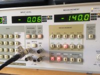
Here are the THD and THD+N measurement carried on my Shibasoku AG15B.
Analyser is Panasonic VP-7722A
Level 1Vrms on 100kOhm Panasonic input impedance
400HPF and 80kLPF engaged
cycles / THD+N / THD2 / 2Fo / 3Fo
10 /-112,5 /-135,7 / -140 / -140
100 / -111,7 / -134 / -140 / -140
1000 / -110,5 / -122,3 /-123 / -137,2
10k / -105,6 / -123,6 / -124,2 / -127,6
400HPF only
20k / -99,78 / -114,6 / -117 / -124,6
60k / -95,4 / -104,6 / -105 / -114,2
100k /-90,1 / -94,87 / -94,79 / -111,5
Anything I can do more?
This rescued Shibasoku from a bin looks good to me. I had trouble with noisy output level selector.
Any simple possible tweak?
PFB
Last edited:
I made an error in HPF vs frequency selection.
Level 1Vrms on 100kOhm Panasonic input impedance
80kLPF only engaged
cycles / THD+N / THD2 / 2Fo / 3Fo
10 /-108,3 /-119,2 / -128,2 / -133,9
100 / -108,9 / -121,4 / -120,7 / -140
400HPF and 80kLPF engaged
1000 / -110,5 / -122,3 /-123 / -137,2
10k / -105,6 / -123,6 / -124,2 / -127,6
400HPF only
20k / -99,78 / -114,6 / -117 / -124,6
60k / -95,4 / -104,6 / -105 / -114,2
100k /-90,1 / -94,87 / -94,79 / -111,5
PFB
Those numbers look consistent with what I usually get. 1V will not get as low a noise floor. 3V is usually the optimum for most analyzers. 10V is best for the AG16. I have also noticed that the switches for the attenuator in mine need contact cleaning to get the lowest distortion. I believe the AG16 uses relays for the attenuation.
If you can figure out the DC offset adjustments you may be able to get a significant reduction in distortion but adjusting them, however you may end up with some DC offset at the output. A schematic would help a lot in figuring out how to optimize the adjustments. I do have some reverse engineering on these oscillators I can share.
If you can figure out the DC offset adjustments you may be able to get a significant reduction in distortion but adjusting them, however you may end up with some DC offset at the output. A schematic would help a lot in figuring out how to optimize the adjustments. I do have some reverse engineering on these oscillators I can share.
It would be nice to see more detail, even schematics or at least a block diagram in the article. A bit long on boast and short on detail. He gets THD+N of 0.0004% at 1kHz and 0.00075% at 20kHz. This is about the same performance as my THD analyzer designed and built 35 years ago with 5534s.
Cheers,
Bob
- Home
- Design & Build
- Equipment & Tools
- Low-distortion Audio-range Oscillator