Bob I have rather curious problem you might be able to help me with.
My SVO is tuned with current dacs, (Mdac). In each range I can tune the full range from 0 to
65535 on the dac (16 bit) 0 to 2mA at with 10V on the reference pin. At a 3.5Vp that would be 0 to 700uA. The dac's full on equivalent resistance is 5k. In the highest range the caps are 330pF. I can only get the dac out to a count of 20,000 (70kHz). After that the oscillator become unstable and goes to clipping. If I bypass the dacs with 5k resistors the oscillator is stable at 120kHz so I know there is no problem with the agc or other. It's very difficult to
trouble shoot. What's going on? Is the dac's capacitance getting in the way? Cout 200pF code dependent.
I wonder if adding a small series resistance on the output of the dac might help.
Attachments
Last edited:
Demian was asking if a SVO can run at sub audio frequencies.
I have this one running at 0.357Hz stable. So yes.
?? I had a KH 4024 SVO (I think, it's been years) that would work to .001 Hz. Those also had essentially instant switching on ranges. It may have been someone else asking.
I'm impressed with your progress.
?? I had a KH 4024 SVO (I think, it's been years) that would work to .001 Hz. Those also had essentially instant switching on ranges. It may have been someone else asking.
I'm impressed with your progress.
Thanks Demian.
I thought it was you. Question answered to whoever asked then.
I think I can solve the Mdac tuning problem by using larger value tuning caps.
This will better swamp the dac's parasitic capacitance but it does mean having to use larger currents for tuning which in turn loads the op amps more. I guess it's a trade off of stability for distortion. Once this is done I'll look into a different tuning arrangement. I only need to switch resistor to ground using resistor T networks or R2R.
Cheers.
Bob I have rather curious problem you might be able to help me with.
My SVO is tuned with current dacs, (Mdac). In each range I can tune the full range from 0 to
65535 on the dac (16 bit) 0 to 2mA at with 10V on the reference pin. At a 3.5Vp that would be 0 to 700uA. The dac's full on equivalent resistance is 5k. In the highest range the caps are 330pF. I can only get the dac out to a count of 20,000 (70kHz). After that the oscillator become unstable and goes to clipping. If I bypass the dacs with 5k resistors the oscillator is stable at 120kHz so I know there is no problem with the agc or other. It's very difficult to
trouble shoot. What's going on? Is the dac's capacitance getting in the way? Cout 200pF code dependent.
I wonder if adding a small series resistance on the output of the dac might help.
Hi David,
I'm familiar with this issue. In my DIY THD analyzer (on my website), on the highest range the range capacitors are 200pF (200kHz range). I needed to put 68 ohms in series with them for proper operation. I believe this has to do with accumulating phase shift in the op amps (I used 5534s).
Hope this helps.
Cheers,
Bob
Thanks Bob.
My SVO is tuned with current dacs, (Mdac). In each range I can tune the full range from 0 to 65535 on the dac (16 bit) 0 to 2 mA at with 10 V on the reference pin. At a 3.5 Vp that would be 0 to 700 uA. The dac's full on equivalent resistance is 5k. In the highest range the caps are 330 pF. I can only get the dac out to a count of 20,000 (70 kHz). After that the oscillator become unstable and goes to clipping. If I bypass the dacs with 5k resistors the oscillator is stable at 120 kHz so I know there is no problem with the AGC or other. It's very difficult to trouble shoot. What's going on?
I have already discussed this with you back then when you were using the lamp multiplier. The issue is the "Q enhancement" effect of the state-variable topology, which drives the leveling loop out of its authority range at high frequencies.
The "Q enhancement" stems mostly from finite GBW of the opamps. Besides the series resistor for the integrator caps which Bob mentiones it is possible to adress this (IME more effectively) by the addition of a capacitor in the high-pass stage (C1512 in the SG505, C2503 in the System One). Select the capacitor value such that the output of the multiplier is as close to zero as possible acrosss all frequencies.
Doing this compensation is absolutely essential, as otherwise the required authority of the leveling loop becomes hopelessly large.
Samuel
Samuel as you recall I brought the Q enhancement issue and it's effects to you. You argued against using the compensation for weeks until I pointed out it was used in the sys1 then you took a closer look. It is in there. The problem was I had too much decoupling between the multiplier and osc to reach 100kHz. Not enough multiplier authority. The problem was solved a week ago.
Not wanting to give up the amount of decoupling used I found it sufficient to add a series RC in parallel with the decoupling resistor in addition to the 'Q' enhancement compensation cap as you described. This allows the use of greater decoupling at lower frequencies while satisfying the needed authority at frequencies above 15kHz.
Not wanting to give up the amount of decoupling used I found it sufficient to add a series RC in parallel with the decoupling resistor in addition to the 'Q' enhancement compensation cap as you described. This allows the use of greater decoupling at lower frequencies while satisfying the needed authority at frequencies above 15kHz.
I have already discussed this with you back then when you were using the lamp multiplier. The issue is the "Q enhancement" effect of the state-variable topology, which drives the leveling loop out of its authority range at high frequencies.
The "Q enhancement" stems mostly from finite GBW of the opamps. Besides the series resistor for the integrator caps which Bob mentiones it is possible to adress this (IME more effectively) by the addition of a capacitor in the high-pass stage (C1512 in the SG505, C2503 in the System One). Select the capacitor value such that the output of the multiplier is as close to zero as possible acrosss all frequencies.
Doing this compensation is absolutely essential, as otherwise the required authority of the leveling loop becomes hopelessly large.
Samuel
This is with a sheet of grounded aluminum foil over the SVO board.
All else the same.
I guess I can live with this. I'd rather see the disco into the noise floor but it is 10kHz.
Rick I think I'm just going to build an enclosure out of FR4 for the time being. Since I'm not making boards anymore I have to do something with all the copper clad I have laying around.
Compared to the cost of aluminum enclosures these days the copper clad is probably cheaper.
If I had a source for aluminum mill stock here some aluminum bar with plate on the top and bottom would do. Just screw it all together. I'm getting tier of living in a small town. Cookie tins are starting to look appealing.
Cheer,
I like Par-Metal. Par-Metal
I think $100 or so is reasonable for a really good EMI and RFI resistant 1U box.
I like Par-Metal. Par-Metal
I think $100 or so is reasonable for a really good EMI and RFI resistant 1U box.
Thanks Dirkwright.
Are these all 19" wide? Do they do smaller enclosures?
No time look at the moment. Just home for lunch break.
Thanks Dirkwright.
Are these all 19" wide? Do they do smaller enclosures?
No time look at the moment. Just home for lunch break.
Yes, they have a desktop series. We use those for our boxes right now, but we want to start making our own.
Update on ADC efforts-
I made changes to the EMU 1212 and it got a little better but its still not stable and not near what I can get from the AK5394A. I will abandon that direction and boot the stuff back out eBay, chalking it all up to experience (unless someone wants a modded emu 1212).
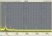
Below is what I can get using one of Viktor's oscillators. I get similar from the modded KH4400. Somehow I'm getting better results than AKM has been able to. I need to find a way to make sure what I'm seeing is not some distortion cancellation.
At this level even a small nonlinearity on the input Z creates measurable distortion. Probably affects the oscillators as well.
I'm working on an upgrade board for the Juli@. I have most of the details worked out now. I'll be assembling the schematic shortly. The actual layout may take a while (unless some volunteer with time steps up).
I made changes to the EMU 1212 and it got a little better but its still not stable and not near what I can get from the AK5394A. I will abandon that direction and boot the stuff back out eBay, chalking it all up to experience (unless someone wants a modded emu 1212).
Below is what I can get using one of Viktor's oscillators. I get similar from the modded KH4400. Somehow I'm getting better results than AKM has been able to. I need to find a way to make sure what I'm seeing is not some distortion cancellation.
At this level even a small nonlinearity on the input Z creates measurable distortion. Probably affects the oscillators as well.
I'm working on an upgrade board for the Juli@. I have most of the details worked out now. I'll be assembling the schematic shortly. The actual layout may take a while (unless some volunteer with time steps up).
Attachments
For what it's worth, I was directed to a small company called Ross Martin:
More Ear Gear
They make ADC's, DAC's and other interfaces for not a lot of money. For the ADC they use the PCM4222 and the DAC uses the PCM1794a. I have no relation to their business. I'm only planning getting some of their gear because it's reasonably priced for what you get and I thought I'd share.
I think the answer is definitely... no. The distortion products you see in the spectrum I've posted are mainly (or entirely) due to the peak detector, whose time constant is zero - no filtering at all means very low settling time (which is good), buy the price you have to pay is that all the harmonics produced by the full wave rectifier are injected in the level control loop, i.e. in the output signal. In order to lower the output THD you have to set up an integrating loop - maybe you can try the one from the JLH's original design:
View attachment 263922
it's a Wien Bridge ring-topology (in order to get rid of the opamp common-mode THD), and the amplitude control loop is based on a canonical peak-detector/integrator chain (whose time constant you'll have the to tailor in order to suite your needs - ie freq range and output amplitude).
L.
The desired time constant can be achieved simpler, replace the LED with an incandescent lamp. That requires an additional transistor for driving.
Further I used instead of a rotary switch 5 inexpensive surplus dual reed relays and a simple TTL "logic" 1 of 5 that drives the relay coils and the range
indicator rectangular LEDs. However one should not attempt to save any cost regarding the caps and the dual ganged pot.
The desired time constant can be achieved simpler, replace the LED with an incandescent lamp.
Right - did you measure generator's THD with the lamp based AGC loop?
L.
Thanks Dirkwright.
Are these all 19" wide? Do they do smaller enclosures?
No time look at the moment. Just home for lunch break.
Here:
Par-Metal
I get them without vent holes. I recommend either clear or gold alodine finish, since it's conductive. Alodine is also good primer for paint, if you choose. They also make custom sizes.
Pls do design one... PLS !! We need one. You'll get plenty of help. Many of us are in the final quarter of the game before the buzzer. Getting down our experience is something important... Now we have the world watching and listening via the WWW/Internet. A once in a life-time opportunity.
Thx-RNMarsh
Ya know, when I was younger, I always wanted to learn about electronics.
Now, I'm older and trying to learn and have come a long long way; and,
I know too that I'm on the 3 period of the game and appreciate all that
everyone has to offer, I watch, listen, and learn, and hope you don't mind
if I ask a bunch of questions with "obvious" answers...
or
Just enjoy interacting because I appreciate your efforts too.
Sync
I made changes to the EMU 1212 and it got a little better but its still not stable and not near what I can get from the AK5394A. I will abandon that direction and boot the stuff back out eBay, chalking it all up to experience (unless someone wants a modded emu 1212).
Below is what I can get using one of Viktor's oscillators. I get similar from the modded KH4400. Somehow I'm getting better results than AKM has been able to. I need to find a way to make sure what I'm seeing is not some distortion cancellation.
At this level even a small nonlinearity on the input Z creates measurable distortion. Probably affects the oscillators as well.
I'm working on an upgrade board for the Juli@. I have most of the details worked out now. I'll be assembling the schematic shortly. The actual layout may take a while (unless some volunteer with time steps up).
The EMU 1212M is NLA apparently. Anything similar that is as good?
Ya know, when I was younger, I always wanted to learn about electronics.
Now, I'm older and trying to learn and have come a long long way; and,
I know too that I'm on the 3 period of the game and appreciate all that
everyone has to offer, I watch, listen, and learn, and hope you don't mind
if I ask a bunch of questions with "obvious" answers...
or
Just enjoy interacting because I appreciate your efforts too.
Sync

- Home
- Design & Build
- Equipment & Tools
- Low-distortion Audio-range Oscillator