WRT VA & temp rise - that's right, so all you have to know is a) what the
regulation spec is and b) what the magnetization current is - no more
cheating. A poor regulations spec will indicate high OP impedance and high MC
will show a poor core mat or a wind that is running the core too hard.
Yes and by reducing the wire dia the regulation falls apart.
Not exactly.
A core material that is run at too higher magnetization level or flux will be
doing it with zero load on the OP or full load. Buying 2 x VA will get you better
regulation but it may not get you better wave form from poor core mat, high
leakage inductance, or running the core 'too hard'.
The best strategy is to corectly spec the transformer by knowing core
material, magnetization level, regulation spec, etc.
I always find this info out and you would be amazed at the variance of
design parameters between manufacturers.
That doesn't work with cheap-o transformers with no clue given as to who made it let alone any 'real' data on the transformer other than VA, volts/amps and primary/sec voltage and configuration and mounting dimensions.... The typical things you get from low cost retail marketing/sales outlets. If you can deal directly with a well known mfr and order from their knowledgeable reps... then your engineering approach works best.
-RM
Looks to me like the LT1468 is just an upside-down AD797. They didn't even bother to change the transistor numbering scheme.
Topology is same --- Simplified Schematics all are similar. Differences are in the (not shown) details. In practice they each need to be finessed to get each to work best... so something is different that the Simplified schematics don't show.
Thx-RNMarsh
Last edited:
Looks to me like the LT1468 is just an upside-down AD797. They didn't even bother to change the transistor numbering scheme.
There's a lot more to these op amps than what's shown here. What's in the data sheets are simplified equivalents.
Topology is same --- Simplified Schematics all are similar. Differences are in the (not shown) details. In practice they each need to be finessed to get each to work best... so something is different that the Simplified schematics don't show.
Thx-RNMarsh
We must have been typing at the same time.
when you approach a corner freq the distortion rises. A characteristic of opamp/nfb filter topologies. This is what Demian noticed. Its due to lowered nfb thus an increase in distortion.
Thx-RNMarsh
Bear in mind that what I said about active filter sensitivity increasing with Q also applies to distortion from the op amp. Increased sensitivity to anything is a bad thing.
Cheers,
Bob
I think Richard answered the question to your satisfaction but for the benefit of readers stumbling on this thread in the future it's "Operational Amplifier Distortion" (October 19, 2009) at
http://www.sg-acoustics.ch/analogue_audio/ic_opamps/pdf/opamp_distortion.pdf There's some additional interesting links on Sam Groner's hosting page "IC OpAmps" at SG-Acoustics · Samuel Groner · IC OpAmps
Dale
Thanks! This is good stuff.
Cheers,
Bob
Bear in mind that what I said about active filter sensitivity increasing with Q also applies to distortion from the op amp. Increased sensitivity to anything is a bad thing.
Cheers,
Bob
yes, got it.
Thx-Richard
Does an Mdac have sufficient performance for the low distortion instrument we are seeking here?
I wouldn't use an Mdac for output attenuation or gain control of an amplifier.
Relays would be much better for this task and considering the cost of even the low grade Mdacs the relay approach might be about the same cost. Another pro for Mdacs is a 16 bit Mdac uses 50uA supply current. The equivalent using relays is in the order of 350mA or more.
Mdacs have there place but they are not perfect. The smaller Mdac have much higher noise than the one I'm using. It would be nice if the digital audio stuff was more versatile.
MDAC-
In a sense even this is a multiplying DAC: http://media.digikey.com/pdf/Data Sheets/NJR PDFs/MUSES72320.pdf It changes the gain based on the input code. For this application how much gain range is needed? Are you tuning with the mdac as well? Is it servo/disciplined to a reference?
Demian does the Boonton servo the frequency on a continuous basis or does it just drive it to a set point and then stop?
Since it can lock and hold to 5+ decimal points it must servo. Open loop would not get there. It has an optical feedback to the microprocessor for the frequency trim and a 12 bit DAC to tune with. I could look at the tuning voltage the next time I have one open to see what it does.
Does a DAC into an analog multiplier count as an "MDAC"?
Does a DAC into an analog multiplier count as an "MDAC"?
Since it can lock and hold to 5+ decimal points it must servo. Open loop would not get there. It has an optical feedback to the microprocessor for the frequency trim and a 12 bit DAC to tune with. I could look at the tuning voltage the next time I have one open to see what it does.
Does a DAC into an analog multiplier count as an "MDAC"?
Probably not by definition. All the Mdacs I've seen are R2R dac that allow an analog signal to there reference pin. The DAC is analogous to the Vc of an analog multiplier. If used this way.
A 12 bit dac is only 4096. This must just be used for fine frequency tuning in the Boonton.
Is the dac the tuning element?
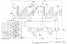
Boonton 1120 oscillator
Here is the complete circuit. There are 8 fets for resistor selection and 4 caps that are switched with FETs for the main tuning. I think the frequency selection is binary, not decimal but the micro hides that. The DAC is used for fine tuning. Its on a different board and comes in through the fine tune connection.
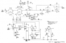
The track and hold/sample and hold agc is on the second sheet. Its pretty simple really and works from 10 Hz to 140 KHz.
The Boonton is a mid-1980's design and I'm sure there are better parts for the special functions today.
Here is the complete circuit. There are 8 fets for resistor selection and 4 caps that are switched with FETs for the main tuning. I think the frequency selection is binary, not decimal but the micro hides that. The DAC is used for fine tuning. Its on a different board and comes in through the fine tune connection.
The track and hold/sample and hold agc is on the second sheet. Its pretty simple really and works from 10 Hz to 140 KHz.
The Boonton is a mid-1980's design and I'm sure there are better parts for the special functions today.
Attachments
Here is the complete circuit. There are 8 fets for resistor selection and 4 caps that are switched with FETs for the main tuning. I think the frequency selection is binary, not decimal but the micro hides that. The DAC is used for fine tuning. Its on a different board and comes in through the fine tune connection.
The track and hold/sample and hold agc is on the second sheet. Its pretty simple really and works from 10 Hz to 140 KHz.
The Boonton is a mid-1980's design and I'm sure there are better parts for the special functions today.
It's a typical track and hold and proportional controller used. What's interesting is the very very long integrator time constant. Shunting the integrator input to ground with those resistor values will produce a very low glitch. This might be a better way to do a pulsed integrator. I find leaving an integrator input open for most of the cycle time allows pick up of noise because integrator gain increases proportionally as the frequency approaches DC. I've noticed a high sensitivity to 60Hz and 120Hz and other low frequency noise. This noise is communicated to the multiplier and in turn to the oscillator. The sensitivity lessens considerably if the integrator is in a state of change. Inducing a small controlled amount of ripple,(sawtooth waveform), on the integrator achieves this even if it's just 10uV or so.
Last edited:
Here is the complete circuit. There are 8 fets for resistor selection and 4 caps that are switched with FETs for the main tuning. I think the frequency selection is binary, not decimal but the micro hides that. The DAC is used for fine tuning. Its on a different board and comes in through the fine tune connection.
The track and hold/sample and hold agc is on the second sheet. Its pretty simple really and works from 10 Hz to 140 KHz.
The Boonton is a mid-1980's design and I'm sure there are better parts for the special functions today.
I found the manual in my archives.
Both the ALC multiplier and FineTune multiplier are in the leveling loop. This loop does not effect frequency. Are you sure this isn't a fine tune of the level?
Both the 'source' and 'fine tune' connect to the output board.
Last edited:
Sect. 4.79 explains the fine tune function. It ties to the second integrator, not the first so it affects the phase of the second vs. the first. It can tune in 25 milliHertz steps at 1 KHz.
Okay I see what they did now.
So you want me to add servo tuning?
Last edited:
Okay I see what they did now.
So you want me to add servo tuning?
I think the software needed plus a frequency counter and reference oscillator makes that more of a project than the oscillator. Its a nice but not necessary feature. However I really like the synthesizer accuracy and flexibility it provides.
I think the software needed plus a frequency counter and reference oscillator makes that more of a project than the oscillator. Its a nice but not necessary feature. However I really like the synthesizer accuracy and flexibility it provides.
The Booton is nice piece of engineering.
A counter is no problem and tuning can be driven to a set point but it would have to be shut down for measurement. This would be for convenience only.
I wounder if a gyrator type filter would perform better than a Sallen key type.
This is what Filter Solutions came up with.
Passive, GIC, Akerberg Mossberg.
I'm not sure about gyrator/GIC--both use noninverting opamp configurations and thus are unlikely to be suitable for low distortion. Akerberg Mossberg is probably an improvement, but at this complexity level one could use a state-variable filter as well.
Looks to me like the LT1468 is just an upside-down AD797. They didn't even bother to change the transistor numbering scheme.
The numbering scheme seems pretty natural. As others have noted, the schematic of at least the AD797 is substantially simplified--you can get a much more detailed view (just omitting bias details IIRC) in Scott Wurcer's AES preprint (no. 3231). A more detailed schematic (which I believe is pretty accurate for the main signal path) for the LT1468 is found in http://cds.linear.com/docs/en/lt-journal/LT1468_1198_Mag.pdf.
Besides the same basic topology, there are substantial practical differences between the two parts:
* The AD797 gives the choice of adding a 50 pF distortion cancellation capacitor, which is not used in the LT1468 (The 10 pF cap C2 is part of the compensation and not used for distortion cancellation). Fortunately the latter uses quite high class B quiescent current in its output stage and thus offers reasonably good load driving capability.
* The AD797 uses much higher bias for the input stage, which results in low voltage noise. Thus it is more suitable for low impedance (< 1 kOhm) sources WRT noise, while the LT1468 offers low current noise and thus excels at higher source impedances.
* The AD797 can be difficult to get stable, particularly with low Z/capacitive feedback networks, low noise gains and with the distortion cancellation capacitor added. The LT part in turn is very well behaved WRT stability, as long as basic good design practice is followed.
* The AD797 offers lower common-mode distortion effects, thus is the part of choice for noninverting configurations.
Samuel
- Home
- Design & Build
- Equipment & Tools
- Low-distortion Audio-range Oscillator