Have you updated your magnum opus on opamp measurements with some of the new ones? I have gotten impressive results from the LME49990 and it seems less fussy than the AD797 (not to mention way cheaper than the AD797 or LT1115 low noise opamps).
Any suggestions for a diff amp with low common mode when starting from a single ended source? I don't see an obvious option. The closest would have an inverter engaged when using a single ended source.
The LT1468 is included and I have tried the 797 and I cant beat the 1468 in being able to tune it to extreamly low distortion levels. The LT lit is old and seems even they didn't know how good it was/is. You might give it a try.
-RM
not everything is negative feedback's fault - at the corner frequency the the reactive component has the highest combination of V across the device and contribution to the outputIn active filters using nfb topologies... at the corners of the filter, the fb is less and thus distortion increases.
Just a small point of interest, perhaps.
-RM
I have definitely seen IMD distortion from a 40 kHz Sallen-Key low pass that went away when the caps were upgraded to polystyrene
again - composite op amps (usually just 2 op amps in a multiloop) can supply enough gain at audio frequencies that passive distortions are dominant
and some composit topologies deal with common mode nonlinearity too http://www.epanorama.net/sff/Misc/O...g to reduce distortion in op-amp circuits.pdf
Last edited:
not everything is negative feedback's fault - at the corner frequency the the reactive component has the highest combination of V across the device and contribution to the output
I have definitely seen IMD distortion from a 40 kHz Sallen-Key low pass that went away when the caps were upgraded to polystyrene
again - composite op amps (usually just 2 op amps in a multiloop) can supply enough gain at audio frequencies that passive distortions are dominant
and some composit topologies deal with common mode nonlinearity too http://www.epanorama.net/sff/Misc/Op-Amps/Using%20supply%20bootstrapping%20to%20reduce%20distortion%20in%20op-amp%20circuits.pdf
Parts affects --- that is all a given. I am fairly certain that I know this already about parts - esp caps and voltage drops across them. What I said applied even if you had perfect C's... sort of an inherent limitation to certain filters with RC in nfb when the margin of OLG and closed LG is degraded. It is a topology limitation of some active filters circuits. Might use a combo of active and passive and not all in one opamp circuit. maybe your composit can fit the bill.
All Demian has to do is change the caps he has in the circuit and see if the affect near the corner is changed/improved or not.... caps or topology or both.
Thx-RNMarsh
Last edited:
Samuel, attached the filter board schematics and the 400 Hz HP I build. Demian already noticed that replacing U8 by a FET input lowered the distortion and he attributed it to lowering the current through the intergrated switches (LF13201).
It looks to me as if the input impedance was determined by the filter topology and impedance level rather than the opamp choice, but I'd need to look into it in more detail.
If you want to investigate this we'd first need to find out whether the distortion is inherent in the filter, or an effect which shows up just when switched in with the FET switches. You could measure its distortion vs. frequency outside the box, with the appropriate operating level as it is used inside it.
If the filter is the cause, check the capacitors--C0G (preferably 100 V rating) would be my choice, polyester a no-go. The topology is inherently not suitable for low distortion because of the noninverting topology. Reducing the impedance level of the feedback network should lower distortion somewhat (although it might increase the contribution of the FET switches); another possibility is to place a matching impedance network in series with the negative input, such that both inputs see equal impedance. Driven supply rails are very effective, but equally complex.
If the switches are the main contributor, there's probably not much to do besides going for better FETs or relays, as you already noted.
Have you updated your magnum opus on opamp measurements with some of the new ones? I have gotten impressive results from the LME49990 and it seems less fussy than the AD797 (not to mention way cheaper than the AD797 or LT1115 low noise opamps).
No; as it stands the time to measure an opamp is just too high, and life has become very busy. I'm toying with the idea of trying to get funds from foundations such that I could automate the measurement procedure, and spend some payed time for it.
I've been focusing on composite opamps, which, as JCX notes above, can offer distortion performance way beyond casual feedback networks and layout effects.
Any suggestions for a diff amp with low common mode when starting from a single ended source? I don't see an obvious option. The closest would have an inverter engaged when using a single ended source.
What has become known as "SuperBal" would be my choice; instead of grounding the resistor divider network of a standard diff amp, drive it with an inverted version of the output signal. See Pro Audio Design Forum • View topic - Balanced Inputs, third pic from top (a simpler version without variable gain just needs 6 resistors total).
The LT1468 is old and seems even they didn't know how good it was/is.
The audio market is probably just too small for them to consider...
Samuel
The LT1468 is included and I have tried the 797 and I cant beat the 1468 in being able to tune it to extreamly low distortion levels. The LT lit is old and seems even they didn't know how good it was/is. You might give it a try.
-RM
Hi Richard,
I apologize if I've missed something, but where is this "magnum opus" of op amp evaluation that you have created?
Cheers,
Bob
not everything is negative feedback's fault - at the corner frequency the the reactive component has the highest combination of V across the device and contribution to the output
I have definitely seen IMD distortion from a 40 kHz Sallen-Key low pass that went away when the caps were upgraded to polystyrene
again - composite op amps (usually just 2 op amps in a multiloop) can supply enough gain at audio frequencies that passive distortions are dominant
and some composit topologies deal with common mode nonlinearity too http://www.epanorama.net/sff/Misc/O...g to reduce distortion in op-amp circuits.pdf
Just to add a further point. It is well-known that most active filter topologies, particularly the single op amp ones, cause significantly increased sensitivity to passive component values and characteristics, particularly at high values of Q. The increased sensitivity of active filters compared to passive filters is a price we often pay.
However, state variable filters generally have the same sensitivity characteristics as passive filters. This is not to say, however, that gain-bandwidth of the op amps in a state variable filter does not also degrade filter performance and accuracy.
High-order active filters are usually constructed of multiple second-order filters in series, with increasing Q for each section. Odd-order high-order filters generally include one real single pole as well. For reasons of active filter sensitivity described above, sometimes the lower-order sections will be implemented with single op-amp filters while higher-order sections may employ a state-variable filter topology. There is an obvious tradeoff here between the cost of precision passive components (especially capacitors) and the cost of IC op amps.
Cheers,
Bob
The filters being discussed here are completely impedance scalable.
Your not stuck with any particular RC range of values. A single scale factor can be used to
slide the impedance by multiplying the R and dividing the C by the same factor or you can reverse by dividing the R and multiplying the C by the same factor. If passive component value choice can improve distortion by making the cap values larger and resistor values lower then this is easy to do. The driving circuit has to be considered and cost will rise.
No; as it stands the time to measure an opamp is just too high, and life has become very busy. I'm toying with the idea of trying to get funds from foundations such that I could automate the measurement procedure, and spend some payed time for it.
Samuel
Another possibility, if you don't mind lending your jig out, is to see if someone else as well equipped as you are would be willing to do some of the work.
Hi Richard,
I apologize if I've missed something, but where is this "magnum opus" of op amp evaluation that you have created?
Cheers,
Bob
yes.... the context ---- See S.Groner.... its his work being refered to -- a huge undertaking to which we all are grateful. it does include the LT1468 which has turned out to be extreamly low distortion in oscillators/generators and is worth a try also.
-Richard
Last edited:
The type of filter from the posted art uses positive feedback to pull the gain up from the attenuation of the passives. The PFB is complex and not flat.
I read about filter distortion increase a long time ago----- so I looked it up and the AES has one that might help you decide which filter to use.... AESJ "Distortion in Positive and Negative Feedback Filters -Vol 32, Issue 4. 1984. There are others... since it was already 'well known'. .
"It is well known that the harmonic distortion of an active filter is greater than the distortion of the opamp itself...." ..... .....
Thx-RNMarsh
Last edited:
I think Richard answered the question to your satisfaction but for the benefit of readers stumbling on this thread in the future it's "Operational Amplifier Distortion" (October 19, 2009) at. . . where is this "magnum opus" of op amp evaluation that you have created?
http://www.sg-acoustics.ch/analogue_audio/ic_opamps/pdf/opamp_distortion.pdf There's some additional interesting links on Sam Groner's hosting page "IC OpAmps" at http://www.sg-acoustics.ch/analogue_audio/ic_opamps/
Dale
Does this call for a re-evaluation of what's been mentioned in this thread (and others" regarding the use of active notch filters?I read about filter distortion increase a long time ago----- so I looked it up and the AES has one that might help you decide which filter to use.... AESJ "Distortion in Positive and Negative Feedback Filters -Vol 32, Issue 4. 1984. There are others... since it was already 'well known'. .
"It is well known that the harmonic distortion of an active filter is greater than the distortion of the opamp itself...." ..... .....
Thx-RNMarsh
Dale
Does this call for a re-evaluation of what's been mentioned in this thread (and others" regarding the use of active notch filters?
Dale
It might. maybe Audio-Precision has some info or others around here who can shed light on that for us.
-RNM
Here in USA all mains do not all have flat topped waveforms.... only if the transformers are heavily loaded (over loaded)/saturated.
Hey I should have known you guys have perfect sine wave mains
")
WRT over loaded / saturated they are different things. Core magnetization
level is not defined by the load, it is defined by number of Prim windings /
voltage. Yes.. I know you knew that!
Transformer VA Ratings are a great spec to cheat.... Price competition is very high.... more VA/$ is the issue for sales. Here, we go by a set temperature rise to rate VA. A good company will tell you the temp at which they rate VA.
WRT VA & temp rise - that's right, so all you have to know is a) what the
regulation spec is and b) what the magnetization current is - no more
cheating. A poor regulations spec will indicate high OP impedance and high MC
will show a poor core mat or a wind that is running the core too hard.
To cut costs, the core material and wire size are often reduced without changing the VA spec they give.
Yes and by reducing the wire dia the regulation falls apart.
Better to buy 2 X VA to get the VA you want if buying cheap transformers.... especially if there is no temp rating or standards referred to in their rating.
Thx-RNMarsh
Not exactly.
A core material that is run at too higher magnetization level or flux will be
doing it with zero load on the OP or full load. Buying 2 x VA will get you better
regulation but it may not get you better wave form from poor core mat, high
leakage inductance, or running the core 'too hard'.
The best strategy is to corectly spec the transformer by knowing core
material, magnetization level, regulation spec, etc.
I always find this info out and you would be amazed at the variance of
design parameters between manufacturers.
If you want to investigate this we'd first need to find out whether the distortion is inherent in the filter, or an effect which shows up just when switched in with the FET switches. You could measure its distortion vs. frequency outside the box, with the appropriate operating level as it is used inside it.
If the filter is the cause, check the capacitors--C0G (preferably 100 V rating) would be my choice, polyester a no-go. The topology is inherently not suitable for low distortion because of the noninverting topology. Reducing the impedance level of the feedback network should lower distortion somewhat (although it might increase the contribution of the FET switches); another possibility is to place a matching impedance network in series with the negative input, such that both inputs see equal impedance. Driven supply rails are very effective, but equally complex.
If the switches are the main contributor, there's probably not much to do besides going for better FETs or relays, as you already noted.
Samuel
Samuel thanks for the suggestions. I have a spare filter PCB which I will build up with better capacitors (I'm using stacked foil ones at the time, probably not-so-hot polyester). I'll also order some better FET switches, there's a better pin-compatible product out there not too expensive. That way I can switch between filters and see if anything makes a noticeable difference.
If I manage to get rid of the mains hum without using a filter I could even compare the filter with a straight-through wire.
But that will be after xmas - leaving tomorrow for Vienna to get a dose of live concerts
Jan
Why not just try a simple passive filter?
Maybe use a follower for a buffer.
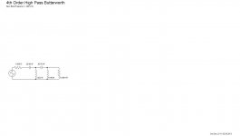
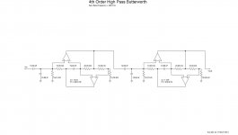
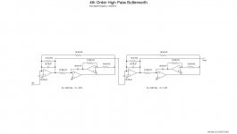
The filter in Jan's post is a fourth order filter. This would be difficult if not impossible to do with a passive RC. It could be done with LC but where would the distortion be then. Air core inductors would be quite large and then there is magnetic field pickup with the inductors.
I wounder if a gyrator type filter would perform better than a Sallen key type.
This is what Filter Solutions came up with.
Passive, GIC, Akerberg Mossberg.
Attachments
Last edited:
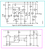
Looks to me like the LT1468 is just an upside-down AD797. They didn't even bother to change the transistor numbering scheme.the LT1468 which has turned out to be extreamly low distortion in oscillators/generators and is worth a try also.
Attachments
- Home
- Design & Build
- Equipment & Tools
- Low-distortion Audio-range Oscillator