What you're observing is exactly the main difficulty with distortion cancellation--the distortion sources observed at these low levels we're concerned with are usually not stable enough for accurate cancellation. That makes IMHO distortion cancellation not the best (as suggested before in this thread), but rather the worst approach to achieve lower distortion. Removing the initial distortion source is far more dependable (and feasible, as I hope my results indicate).
Samuel
I have not attempted to totally eliminate distortion to exteamly low levels with cancellation techniques, only. An approach that seems workable is to get it down a lot with cancel topology and then apply the nfb to it to reach the lowest levels. I think a greater total amount of 'error correction' can be done this way over the widest range of freqs. I think this falls under your thought to rid initial distortion first.... thru many means including cancelling topologies. But I would still rely on nfb to do a lot of the heavy lifting after all other forms of distortion are removed.
-RM
Last edited:
I'm working with three separate oscillators all capable of -127 dB second harmonic per the 725. Since they all have the same limit I suspect that is the 725's internal limit. I'm understandably reluctant to muck around inside the 725. Its really dense and very well made. the attention to detail in its manufacturing is remarkable. Even the relay cans are all meticulously soldered to ground. There is a DC offset trimmer on its input stage and I may fiddle with it. However I'll switch to using the B&K 1607 in front of it for now. I think I need to build a small single frequency version that does what I need- specifically attenuating the fundamental about 20-40 dB so the harmonics are well above the internal limits of the analyzer.
The Shibasoku oscillator (590AR) has all of its tuning components including some of the caps for the AGC on the bottom side of the chassis with a metal plate separating them from the circuitry. The KH4400 doesn't.
My KH4400 is reliably getting to -127dB 2nd H on the 725 after some judicious tuning of the distortion adjust (otherwise as shipped). It has more 3-5 harmonic than the 590AR but they are all low. Viktor's oscillator has the lowest higher harmonics of the three. It also has lower noise than the KH4400, leading me to explore changing the opamps/drive circuitry in the KH4400.
The problem with ever more powerful microscopes is that you keep seeing new things. . .
I was wondering about this trim... otherwise I was going to suggest using this --> maybe try it anyway and leave the existing trim untouched.

The KH4400A I have... does .0001% at 1KHz and .00025% at 10KHz with a couple opamp changes and adding an adj trim in place of a fixed value from the factory. I already outlined this in earlier comments/developments.
The 4402B is 1/2 the distortion by virtue of a different circuit for the reg/control circuitry... the osc part is the same as a 4400. The same sort of upgrades yielded a .00005% at 1KHz and .0001% at 10KHz. Thats about as low as the source in the new A-Prec source/generator.
For the performance, money, time and effort... the used (eBay) K-H 4402B is very hard to beat. And, flexible with amplitude and freq choices. Only the davada and SG designs have potential to do better.
For a little more money, you can buy a better source with an analyzer, from Panasonic (VP-7722A) that is as good or slightly better, typically. Spec'ed for .0001% full scale. Another best buy option.
Thx-RNMarsh
Last edited:
Good point jensH.
Thanks,
Good reminders as to why the caps have the band in the first place -- since tube days. On caps without the band..... I have suggested to put the cap in a metal tube and measure the c from tube to each lead. the one with the highest c is attached to the outer plate/foil.
You might just want to put a grounded, floating metal foil around the body and not connect it to either end of the capacitor plate/foil.
-THx RNmarsh
I did some judicious fiddling with the KH4400. I got its distortion down some.
The opamp swap is not simple. The active follower (a band-aid for the the opamps available in 1985) has been tuned to the specific opamps. I tried several opamps until I figured out the distortion was actually oscillation I could not see. For the main output opamp (U183) to be stable with an LT1115 or LME49710 I had to bypass R186 with about 22 pF. The output is still flat to .05 dB at 100 KHz. Then either will work. I also got the AD797 to work here. For the inverting opamp (U141) it seems less sensitive. A simple swap works with either the LT1115 or the LME49710. For the osc. output opamp (U125) I had to do more major surgery. I needed to get the follower Q127, out of the loop it seems. I put a jumper from R125 and R126 to TP10 and it all got stable. I tried other variants and they didn't work. This only works with the LME49710. After it was all stable I tweaked the JFET for a second harmonic null.
End result- 1 KHz 2nd harmonic seems to be about -132, the third about -137 and THD + N in a 30 KHz band (below the meter on the 725) at about -114 dB? or somewhere around .0002%. Looking at it the second harmonic is at about the level of the nulled fundamental. THD alone seems to be -127 dB (.00005% if you are counting). The meter is sitting at the lower peg so I am extrapolating from a measurement of the analysis output. Any measurement below -100 is suspect, below -110 is very suspect (as I'm sure SG would confirm).
Without the ability to null the second harmonic getting to this level probably isn't possible. I think the fact that this uses a similar AGC to Viktor's oscillator (different implementation of the feedback around the FET) is why it works.
Comparable numbers to what i got. I think I used a 1468. Its in the story board here somewhere. You can do a little better numbers with the 4402B. I like the KH for the fact that it is upgradable in a straight forward engineering way and is flexable. With 2 of KH at my disposal, I could use them for IM testing as well.
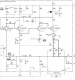
Can you mark up the schematic with your changes and post it here.
-RM
Can you mark up the schematic with your changes and post it here.
-RM
The distortion in the meter circuit of the HP-334A can be reduced thru cancellation. The input stage is a buffer which introduces about 6dB of the total distortion. So, I went at the meter circuit again. R36 (390k)- the nulling value was replaced with a multi-turn pot of larger value and adjusted for null. Most affected was the 3H and it was dropped into the floor of the QA400.
The 2H will be harder. But it is now at about -100dB.
Thx-RNMarsh
The 2H will be harder. But it is now at about -100dB.
Thx-RNMarsh
Attachments
Final thoughts for the 334A --- the auto-null circuitry with its differential input circuits, measures in at -110dB harmonic levels. So, that is the lower resolution limit of the instrument. The input circuits are single-ended -- really the volt-meter frontt-end that drives the notch filter can be bypassed and go direct to the null circuit input. Thats what i did and saw -110dB. If you just add the trim adj and fiddle with the input buffer and meter/null driver's bias control and make the panel meter disconnect..... these changes can get you to -100 to -105dB at the monitor output port.
This is a heavy and strong built piece of equipment and a reliable work horse. The best feature is the tunability of the notch and that allows for fine tuning and flexibility to match any osc/generator, exactly. Or, to tune out any individual harmonic. You could also use it as a fundemantal notch for an ADC input by adjusting the notch depth in manual mode. It seems to be very stable after warm-up. In auto-null mode, the depth of the notch is about -80-85dB. For the typical cost of $50 it can be helpful to anyone on a tight budget.
Thx-RNMarsh
Last edited:
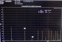
Source testing below -100dB with AP-2722
I finally got the Audio-Precision 2722 up and running. I can now compare tests with it to other analyzers (e-MU, QA400, HP, ShibaSoku etc). Especially, interested in the differences below -100dB.
Then we will have distortion info regarding gen/source levels measured by various equipment.
Thx-RNMarsh
I finally got the Audio-Precision 2722 up and running. I can now compare tests with it to other analyzers (e-MU, QA400, HP, ShibaSoku etc). Especially, interested in the differences below -100dB.
Then we will have distortion info regarding gen/source levels measured by various equipment.
... sounds very interesting
")
Jesper
I was wondering about this trim... otherwise I was going to suggest using this --> maybe try it anyway and leave the existing trim untouched.
View attachment 367660
Guess who has drawn this schematic
?Samuel
Another little teaser from my oscillator design: Here's the input-referred distortion voltage of the amplifier which I intend to use for the output driver stage, at +24 dBu into 200 Ohm load:
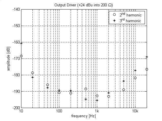
This is measured by operating the amplifier at 60 dB noise gain, then referring the distortion measured at the output to the input (same basic procedure as in my opamp measurement series). Despite the high noise gain, the distortion of the amplifier is very close to/below the residual of the SYS-2722. The only distortion clearly attributable to the amplifier is the 3rd harmonic at and above 5 kHz.
The amplifier is operated at a maximum noise gain of about 10 dB, so its distortion contribution is well below -140 dB over the entire audio frequency range. Clearly this stage will be dominated by distortion in the feedback network and/or layout effects.
The topology is a composite opamp, with the first stage a OPA1611 and the second a discrete high-speed (unity-gain bandwidth ~35 MHz) design. At 100 kHz, the gain-bandwidth product of the composite opamp is 1 GHz, at lower frequencies even more.
Samuel
Guess who has drawn this schematic
Samuel
The one and only?
The usual problem with a composite solution is stability. A GBW of 1 GHz would be very difficult to close a loop around in practice. Also composite amps can be really difficult to manage in overload. I'm sure many of use will be really interested when you lift the veil. . .Another little teaser from my oscillator design
The topology is a composite opamp, with the first stage a OPA1611 and the second a discrete high-speed (unity-gain bandwidth ~35 MHz) design. At 100 kHz, the gain-bandwidth product of the composite opamp is 1 GHz, at lower frequencies even more.
Samuel
I went to your Opus on opamp measurement and saw that it has not been updated recently and is missing some of the newest entries in the audio opamp sweepstakes. I was going to make a board that does a subset of your tests, ones that are pretty easy to do with less than an AP available. You are using 60 dB noise gain. Do you think increasing the noise gain to 80 dB will work with these opamps? I want to get the distortions well out of the mud so they can be observed with common soundcard stuff.
The usual problem with a composite solution is stability. A GBW of 1 GHz would be very difficult to close a loop around in practice. Also composite amps can be really difficult to manage in overload. I'm sure many of use will be really interested when you lift the veil. . .
I went to your Opus on opamp measurement and saw that it has not been updated recently and is missing some of the newest entries in the audio opamp sweepstakes. I was going to make a board that does a subset of your tests, ones that are pretty easy to do with less than an AP available. You are using 60 dB noise gain. Do you think increasing the noise gain to 80 dB will work with these opamps? I want to get the distortions well out of the mud so they can be observed with common soundcard stuff.
An oscillator is a very controlled use of a composite amp. Overload may not be an issue if the amp only sees an attenuation circuit. The attenuation decouples the amp from the load. It is a different story if the amp were direct out. Then we have no control of load.
I have a composite amp in spice. Even there it's difficult to satisfy all load conditions.
In a controlled system like an oscillator you can be more successful. The composite amp in the LTC super oscillator http://cds.linear.com/docs/en/application-note/an67f.pdf pg. 62 is a good example. It is also clear that making it work across a broader band is difficult. I am really interested in Samuel's execution.
For a general purpose amplifier getting a composite to behave well is very challenging.
For a general purpose amplifier getting a composite to behave well is very challenging.
I went to your Opus on opamp measurement and saw that it has not been updated recently and is missing some of the newest entries in the audio opamp sweepstakes. I was going to make a board that does a subset of your tests, ones that are pretty easy to do with less than an AP available. You are using 60 dB noise gain. Do you think increasing the noise gain to 80 dB will work with these opamps? I want to get the distortions well out of the mud so they can be observed with common soundcard stuff.
I don't think there will be fundamental difficulties with 80 dB noise gain--I have a test jig for DC open-loop gain measurements which uses even 100 dB. The problem with high noise gain is decreasing bandwidth. Even with a 100 MHz GBW part the bandwidth is restricted to 10 kHz if operated at 80 dB noise gain, so accurate measurement of THD is limited to 1-2 kHz. On my current test jigs I have jumpers to set the noise gain from 20 dB to 60 dB in 10 dB steps, so high-frequency distortion can be accurately measured even for opamps with modest GBW.
Samuel
- Home
- Design & Build
- Equipment & Tools
- Low-distortion Audio-range Oscillator