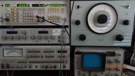
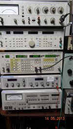
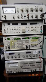
If you put a 6 dB pad between the oscillator and the analyzer (assuming the pad and interface are always 600 ohms), then the 2nd harmonic should go down by 6 dB if is coming from the analyzer in most cases, where the working level in the analyzer is determining its distortion (not sure this will apply to the control voltage ripple contribution, however). If the 2nd harmonic stays the same, it is probably from the oscillator. This is just a rough test and there may be exceptions.
For the 3rd, distortion should theoretically go down by 12 dB if the dominant source of distortion is in the analyzer. Above caveats apply.
In both these tests, we assume anayzer input attenuator remains the same. We also assume that the 2nd and 3rd are measured with a spectrum analyzer at the residual output with sufficiently narrow bandwidth that noise will not influence the result.
It is important to appreciate under which conditions the level dependence you mention (proportional to fundamental level for the 2nd harmonic, and proportional to the square of fundemental level for the 3rd harmonic) holds. It only applies to circuits which are usually described as "weakly nonlinear". I don't recall the theoretical details (if you're not afraid of serious math check out Wambacq and Sansen, "Distortion Analysis of Analog Integrated Circuits", Springer), but it is the condition where the circuit behaviour can be described by Volterra (or in some simple cases by Taylor) series. Typical distortion sources where this is the case are:
* power and voltage coefficient in resistors
* voltage coefficient in capacitors
* class A amplifiers
* multiplier cores based on JFET-VCRs and translinear cells (at least under typical control voltage conditions)
Typical distortion sources which are not "weakly nonlinear", and thus the simple level-to-harmonic relation does not hold, are:
* class AB/B output stages (i.e. about any IC opamp under typical operating conditions)
* AD and DA converters
* iron core inductors and transformers
* rectifiers
* sample-and-hold amplifiers
Above list suggests that we can hardly rely on the level-to-harmonic relation in a distortion analyzer. I've looked into this for a few analyzers I have access to, and indeed I've found that their distortion contribution is often a very complex function of input level. Just as an example, forcing unusually low input levels may cause the contribution at one harmonic to drop, and at the other to rise.
Having said that, I frequently force the AP SYS-2722 into a higher range when doing THD analysis. At least for that particular unit it seems like the distortion contribution is then somewhat lower and more consistent (although THD+N suffers). It also gives a certain degree of confidence--if the measured THD is the same for both the auto-ranging range and the manually forced higher range, the distortion contribution of the analyzer is probably negligible.
Nonetheless, this is no replacement for a notch filter specifically designed for very low distortion if looking below the -120 dB level. A passive filter has not only the advantage of being relatively easy to design for low distortion contribution, but also that the simple level-to-distortion relation should hold very well (unfortunately not for the following amplifier and ADC!). So you can evaluate the filter at say +20 dBu, and extrapolate its distortion contribution to 0 dBu.
Samuel
These are good points, Samuel.
I agree, there is probably little better than a well-designed passive notch filter to weed out some of these effects. I used twin T filters about 2 years ago when I was tweaking my distortion analyzer, and they were very helpful.
Also, if we can bootstrap our confidence level in the low distortion performance of some of the better op amps we are using, we can use some active circuits to help us sort things out further. One example would be if it helps to buffer one or both sides of the twin-T filter. Another would be to build a high-Q bandpass filter to clean up the oscillator. This filter could be of a very similar topology to that of the oscillator, such as state variable, but it would have the distortion advantage over the oscillator of not being degraded by an agc element or agc level detection ripple.
Two years ago, I tried cleaning up my oscillator with a passive parallel resonant filter, but don't seem to recall getting much out of it.
Cheers,
Bob
Null out harmonics from ultra-low THD oscillator -
I used an B&K 1607 variable notch filter to remove a remaining harmonic after tuning out one of the two dominant harmonics. This variable unit is very useful and flexible tool. Wish I had two of them... though they are really BIG to cover low freqs with passive parts.
An osc with a couple twin-T can make the output nearly 'perfect'. Leaving the analyzer to be the weak link in the test system..... ADC/FFT? Or, tune up one of the many very good used commercial analyzers.... which are also very flexible instruments.

Thx-RNMarsh
I used an B&K 1607 variable notch filter to remove a remaining harmonic after tuning out one of the two dominant harmonics. This variable unit is very useful and flexible tool. Wish I had two of them... though they are really BIG to cover low freqs with passive parts.
An osc with a couple twin-T can make the output nearly 'perfect'. Leaving the analyzer to be the weak link in the test system..... ADC/FFT? Or, tune up one of the many very good used commercial analyzers.... which are also very flexible instruments.

Thx-RNMarsh
I checked my stock HP339A last night against my THD analyzer, alternating who is the source, and looking at the relevant residual output on the HP 3580A SA. All at 1kHz.
The 339A oscillator looks fairly good at about 0.0006% THD+N.
The 339A analyzer portion is disappointing, and there may be something wrong with it. It is reading 0.005% and the residual waveform is not that pretty, with harmonic components extending up beyond the 3rd.
Cheers,
Bob
The 339A oscillator looks fairly good at about 0.0006% THD+N.
The 339A analyzer portion is disappointing, and there may be something wrong with it. It is reading 0.005% and the residual waveform is not that pretty, with harmonic components extending up beyond the 3rd.
Cheers,
Bob
I checked my stock HP339A last night against my THD analyzer, alternating who is the source, and looking at the relevant residual output on the HP 3580A SA. All at 1kHz.
The 339A oscillator looks fairly good at about 0.0006% THD+N.
The 339A analyzer portion is disappointing, and there may be something wrong with it. It is reading 0.005% and the residual waveform is not that pretty, with harmonic components extending up beyond the 3rd.
Cheers,
Bob
Your analyzer portion is definately not working right and far out of spec.
The mods I did some month ago help with the residual of the analyzer.
Bob you are very familiar with the quadrature detectors used in the 339a. They are the same as what you used in you analyzer. Give the input buffer to the detectors a bit more gain and I think you will see an improvement. If you upgrade the buffer to a LT1468 you can more bandwidth into the detectors.
The work I did on the analyzer cleaned up the distortion problems so at least there is a accurate measure from the monitor output. Look for parasitic oscillations going on in the analyzer. The 339a is very wide band and it doesn't take much to set it off. The parasitic osc raises the distortion mostly the 2nd and 3rd.
The mods I did some month ago help with the residual of the analyzer.
Bob you are very familiar with the quadrature detectors used in the 339a. They are the same as what you used in you analyzer. Give the input buffer to the detectors a bit more gain and I think you will see an improvement. If you upgrade the buffer to a LT1468 you can more bandwidth into the detectors.
The work I did on the analyzer cleaned up the distortion problems so at least there is a accurate measure from the monitor output. Look for parasitic oscillations going on in the analyzer. The 339a is very wide band and it doesn't take much to set it off. The parasitic osc raises the distortion mostly the 2nd and 3rd.
Thanks, David.
These are very good suggestions!
Best regards,
Bob
Happy to say ---> I just got a portable PC upgrade--- Sony S class with i7 Quad core --- 12GB RAM and all SSD. Win 8 Pro (64 bit);
The QA400 latest software down-loaded fine and the software/hardware worked 100% without a hitch.
-RNM
Tempting the gods of software is dangerous!
When looking at the output of an 339A oscillator into an ADC at various input levels between -3dB to -20dB, there is a large change between the 2H and 3H.
On the ADC/FFT, at -20dB input, the 2H was below the 3H by 5dB. At -10dB input the 2H and 3H were about the same level; At -3dB input, the 2H was >10dB above the 3H.
This isnt a useful characteristic. I want to know the harmonic structure, not just a THD number and if the test equipement changes the DUT harmonic structure, what good is it?
Wiill Demian's interface or davada's changes solve this?. Does the e-MU models (0202 and 0404) do the same thing... showing variations of large amounts of 2H/3H with input level? At what input level is ADC displaying the correct harmonic levels?
Thx-RNMarsh
Last edited:
At what input level is ADC displaying the correct harmonic levels?
That's an easy one: at no input level.
Samuel
You are of course looking at the resolution limit of the a/d. This is where the cat chases it's tail. What you need is a precision oscillator to test the a/d.
That's why I mentioned using multiple locked and phase adjusted oscillators. It is a reciprocal method for looking at the edge of nowhere.
That's why I mentioned using multiple locked and phase adjusted oscillators. It is a reciprocal method for looking at the edge of nowhere.
That's an easy one: at no input level.
Samuel
This is brilliant. Then the Worlds greatest oscillator is the one that puts out nothing.
but indeed at zero input the measurement should be pretty good, usually!
Samuel
Unfortunately at zero input the snr approaches zero and the errors approach infinity. But it shouldn't be a problem if you know what you are doing.
I think the first step would be to know what the actual performance of the oscillator is. When its distortion is so low it becomes quite hard to know what is contributing what. I have measured pots with higher distortion than these oscillators. Ultimately, below -130 dB having confidence in the distortions is very difficult.
Once the level of harmonic generation becomes so close to nothing there may be little to be gained going further. At this stage looking at other nonlinearities may be much more useful. It is inconceivable that any transducer would have distortions within 40 dB of this level. Perhaps a multitone IM test would be more useful and less technically demanding. Its also a more real world situation. A group of musicians playing horns will have a lot of harmonics but should have no sounds below the fundamental. Or perhaps settling time would show issues. Going much further down this road will lead to madness. . .
You are of course looking at the resolution limit of the a/d. This is where the cat chases it's tail. What you need is a precision oscillator to test the a/d.
That's why I mentioned using multiple locked and phase adjusted oscillators. It is a reciprocal method for looking at the edge of nowhere.
This can help with knowing what is what, harmonic-wise. However, it doesnt change the ADC non-linearities which are pretty gross below -100db (or higher). Somewhere in the middle of the ADC operating range it is at its best linearity. Maybe a 40dB range in the middle could be used for measurement purposes. There the changes to the harmonic levels/relationships/structure is fairly constant/stable.
Other-wise, i am inclined to continue to use the swept BP wave - spectrum - analyzer to measure residuals. Even thought the noise floor is more visible. or, other passive notch filter methods though they are not as convenient but are more accurate with various input levels.
This is consistant with Sam G's conclusions when using his Audio-Precision.
Thx-RNMarsh
Last edited:
Why lower noise -
If we go back to #2666 for a moment -- The 339A display shows the affect of a concerted effort to not just lower THD but to lower the noise throughout the osc/analyzer system. the noise floor is now lower than the other analyzers and the 3H can be seen which would have been obliterated with noise on a stock 339A when using a wave/spectrum analyzer to view the residuals. This is why i am interested in lowering the noise of the better AD725D and maybe the VP-7722A (looks like a keeper).
Thx-RNMarsh
Last edited:
- Home
- Design & Build
- Equipment & Tools
- Low-distortion Audio-range Oscillator

