You don't want Ohms you want current.
Yes I know I don't want ohms.
I was just testing it with an ohm meter.
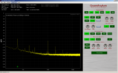
This is the circuit used and spectrum of the output.
For 6Vrms input to the lamp there is a 5.56Vdc output.
At 3Vrms the output drops to 0.823Vdc.
That's not very linear.
I'm concerned about the level of distortion as well.
This is with a 0.1uF feedback cap on the output amplifier.
I's much worse with out the cap.
R is 10M.
For 6Vrms input to the lamp there is a 5.56Vdc output.
At 3Vrms the output drops to 0.823Vdc.
That's not very linear.
I'm concerned about the level of distortion as well.
This is with a 0.1uF feedback cap on the output amplifier.
I's much worse with out the cap.
R is 10M.
Attachments
Last edited:
Here is another possibility-
Using a small micro (Arduino?) with an internal ADC or external ADC to detect the level of the oscillator output and then an internal DAC to send a voltage to the optical link that does the slow control loop for overall leveling. I'm sure linuxworks could tell us if the code is difficult and it could implement whatever PID is necessary to settle as fast as the system can.
One big reason that different frequencies will settle differently is the matching and balance of the R/C networks (and the GBW of the amplifiers). A really interesting possibility once you have a micro is electronic tuning. Using the micro for frequency detection and another 2 quadrant multiplier you could tune the system very precisely.
Here is another possibility-
Using a small micro (Arduino?) with an internal ADC or external ADC to detect the level of the oscillator output and then an internal DAC to send a voltage to the optical link that does the slow control loop for overall leveling. I'm sure linuxworks could tell us if the code is difficult and it could implement whatever PID is necessary to settle as fast as the system can.
One big reason that different frequencies will settle differently is the matching and balance of the R/C networks (and the GBW of the amplifiers). A really interesting possibility once you have a micro is electronic tuning. Using the micro for frequency detection and another 2 quadrant multiplier you could tune the system very precisely.
I tried this with a PIC controller and found that they don't work very well for real time control. They work well for motor control but that is very low frequency.
The module timing for SPI transfer takes a while to set up and so I couldn't get a continuous stream of transfer. The processor is running at 48MHz. The SPI at 12MHz.
DSP I think would be a better approach.
Lt has a couple of high speed ADC which handle the timing for SPI transfer. So it's possible
to do a ADC to MDAC transfer with out a processor and there is no overhead in the timing.
I am planning MDAC tuning for this oscillator and that part will be controlled by a PIC micro.
The PIC is USB and there will be a Windows interface with a frequency counter, tuning and level controls. A cheesy Windows interface but functional. I'm not really a programmer but can do embedded in C.
The preliminary work with the PIC is done already. I just need to get the oscillator going
and that needs an AGC.
I'll try again with an LDR tomorrow and see how it goes. Failing that then I'll get some boards made up at a board house and get on with it.
Cheers,
My Boonton does the frequency trim through an optoisolated link. I get very good phase noise plots with it. If you have the local loop for stabilizing the oscillator then the control loop doesn't need to be very quick at all. For frequency they use JFET switches for both resistors and caps. Today I would use a controlled resistor array and switch the caps with JFETS. Then the final steering would be using a 4 Q multiplier. The PLL code would be the most difficult to get right.
Here is a digital volume control chip that could be used in a control loop for AGC (and frequency trim) http://semicon.njr.co.jp/eng/PDF/MUSES72320_E.pdf The opamps are external so its just resistors and jfets when used that way. Two to a chip so both functions could be managed. There are probably others that could work as well (and lots cheaper, these guys have an opamp thats $50).
My Boonton does the frequency trim through an optoisolated link. I get very good phase noise plots with it. If you have the local loop for stabilizing the oscillator then the control loop doesn't need to be very quick at all. For frequency they use JFET switches for both resistors and caps. Today I would use a controlled resistor array and switch the caps with JFETS. Then the final steering would be using a 4 Q multiplier. The PLL code would be the most difficult to get right.
The PIC has a 10 bit ADC and some are available with 12bit. This might be enough to set the level. 10 bit on 5V is 5mV resolution and 12bit is 1.3mV. The oscillator doesn't need to be sampled ever cycle to do this but we still need a fast sampler to capture the peak.
If the oscillator is running around 3Vrms then it fits into 12 bit over 10V for 2,5mV resolution.
Here is a cheaper solution: http://datasheets.maximintegrated.com/en/ds/DS1882.pdf These are non-volatile so the oscillator could start from where it last was set.
Its a lot worse than the results shown in the left paper/page. Why is that?This is the circuit used and spectrum of the output.
For 6Vrms input to the lamp there is a 5.56Vdc output.
At 3Vrms the output drops to 0.823Vdc.
That's not very linear.
I'm concerned about the level of distortion as well.
This is with a 0.1uF feedback cap on the output amplifier.
I's much worse with out the cap.
R is 10M.
-RNM
Why not two of them in control loop: (A*sin(wt))^2+(A*cos(wt))^2)=A^2, no ripple (in theory)multiplier
Why not two of them in control loop: (A*sin(wt))^2+(A*cos(wt))^2)=A^2, no ripple (in theory)
In a perfect world Dimitri.
The Sin and Cos terms have to be exactly matched or it gets really ugly.
Its a lot worse than the results shown in the left paper/page. Why is that?
-RNM
System as a whole here. Lamp plus detector.
we are very demanding. What you see wound not show on a chart.
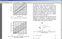
The lumens of a lamp driven from AC is not necessarily linear.
I don't have equipment to measure this.
It shows up in the multiplier gain constant chart.
My Boonton does the frequency trim through an optoisolated link. I get very good phase noise plots with it. If you have the local loop for stabilizing the oscillator then the control loop doesn't need to be very quick at all. For frequency they use JFET switches for both resistors and caps. Today I would use a controlled resistor array and switch the caps with JFETS. Then the final steering would be using a 4 Q multiplier. The PLL code would be the most difficult to get right.
This is an interesting looking IC.
Do you know who sells them?
Are the distortion figures with or without op amps?
The Sin and Cos terms have to be exactly matched or it gets really ugly.
Have you tried it? Even with several percent amplitude mismatch output ripple is likely still much lower than for an average or RMS detector (with the same filtering). And you can easily trim the amplitude match for each range.
The S & H peak detector is cleary better, but also more difficult to implement right.
Samuel
System as a whole here. Lamp plus detector.
we are very demanding. What you see wound not show on a chart.
The lumens of a lamp driven from AC is not necessarily linear.
I don't have equipment to measure this.
It shows up in the multiplier gain constant chart.
Being a test equipment junky, I can loan you the equip to measure Lumens... if you want to know more about this.
For any system, just need to know if it can be linearized easily and affectively.
-RNM
Last edited:
Being a test equipment junky, I can loan you the equip to measure Lumens... if you want to know more about this.
For any system, just need to know if it can be linearized easily and affectively.
-RNM
Thanks Rick.
It doesn't matter that much. I'm interested in the system as a whole.
The lumens for this lamp at 18V is 1.89.
The linearity of the system is more important. How much distortion is added.
There is some signal transmitted by the lamp to the optical sensor and it is this I'm looking at. What saw on the I posted is about 5% distortion. That's too much for such small signal. So I will try something else. The linearity of the device I used depends on the wave length of the source according to the data sheet IIRC. There is either a positive or negative tempco also dependant on the wavelength of the source.
I have some LDR around somewhere but have I no idea what they are. I think I got them from Radio Shack. When they where still called that in Canada.
Last edited:
Have you tried it? Even with several percent amplitude mismatch output ripple is likely still much lower than for an average or RMS detector (with the same filtering). And you can easily trim the amplitude match for each range.
The S & H peak detector is cleary better, but also more difficult to implement right.
Samuel
Hi Samuel,
No I haven't tried it outside spice. What I saw from spice was not to promising.
Some one did try this and posted the results in one of the threads saying the ripple wasn't much better than more conventional methods IIRC.
I don't mind trying anything but then I don't get too far along on this project.
At 1KHz the output from an AD536A is quite acceptable. All harmonic appear to below -130dB. I have to confirm this once I have the Twin T built and my EMU0204 arrives.
Then I have something to compare the QA400 to.
Cheers,
- Home
- Design & Build
- Equipment & Tools
- Low-distortion Audio-range Oscillator