David,
ExpressPCB will accept proprietary output format from their free soft, the board size 3.8 x 2.5 inches only,
33each - normal gerber files from your CAD, e.g. FreePCB; with 33each you are limited with max size 60 sq. inches - but this is pretty large PCB.
My board is quite a bit larger than this. I'll take a look at their other offerings.
I don't what to go to surface mount.
I like expressPCB a lot. Its not real cheap but the boards are good quality and its easy to share the source files. And plenty quick. They arrive just as you thought of the other changes you want to make. I would not use them for leading edge stuff (you can't anyway. . .).
However Canada shipping may make it lots less attractive.
I would do a shipping hop for this. Send to a friend in US and regular post to Canada.
For a final board I don't mind going the expense. But one change or mistake really bothers me.
A home brew board... hack away.
My bother in law just gave me an HP 2840 he no longer uses at his business. This thing is huge and takes up a lot of floor space.
I'll use this for the transparencies. My Samsung laser just wasn't cutting it.
Last edited:
A lamp multplier for SVO
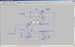
Here is the basic multiplier design.
The multiplier is designed around the lamps resistance curve because we have little control of this. R4 is chosen to center the gains and inverting crossover about the lamps curve.
R6 and R7 set the non inverting attenuation and R4 the inverting attenuation.
The multiplier operates below unity gain. Because the resistance values are low we can take advantage of using one of the ultra low noise op amps available. I chose the OPA1612 because of it's low noise current spec and outstanding distortion spec.
One obvious problem with injecting a DC control voltage or current into a lamp is the introduction of voltage offset appearing at the amplifier's output. Simply adding a blocking capacitor led to phase shift problems within the multiplier which interfered with the oscillator loop. Using two lamps as shown solves this problem. However it is near impossible to match two lamps well enough to keep the offset to a reasonable amount.
Because of this a DC servo loop is added to take care of the last remaining bit of imbalance. The servo forces the current in each lamp to balance, near eliminating
the offset at the multiplier's output. The lamp drivers are a balanced configuration and offer cancellation of ripple and other signals riding on the DC controls signal.
This cancellation takes place at the summing node of the lamps and depends on the current balance of the lamps. The lamp drivers see signal at their outputs through the lamps. Both noise and distortion can be reflected back through the lamps into the multiplier.
For this reason low noise low distortion op amps are chosen.
I have tried other lamps for stabilizing an SVO but the 7220 lamp seems to work best.
The multiplier has been tested with an SVO from 10Hz to 100KHz with a manually set DC voltage at the lamp driver input. I am still working on a suitable ACG for this multiplier. And I need to isolate the performance of the multiplier. I have still yet to determine the TC of the lamps. This is important to know to set an appropriate TC for an AGC. As far as I can tell the AGC TC will have to be ten times longer than the lamp TC.
The distortion performance of this multiplier with an SVO is really quite impressive and well worth the extra complexity of the driver circuitry.
There is more refinement for this multiplier that I haven't included here which has to do with linearizing, (not sure that's a word) the multiplier gain constant. But this is a matter of an additional stage and will be addressed separately.
I've included a cheesy LTspice schematic and the plot of the lamp's curve.
The 7220 has a cold resistance of about 70 ohms.
Cheers,
Attachments
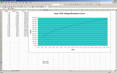
Lamp curves
Here is a zipped file of the xls.
I'd also like to point out that lamps are not the only element that can be used with this multiplier configuration.
thermistors, RDT's, possibly thermocouples or any other heating element like the LT IC mentioned etc. can be used.
One possibility is cancellation of 3rd H of a thermistor?
Signal feedback is possible through the driver amplifiers.
Have fun.
Cheers,
Attachments
Last edited:
SVO with multiplier perfromance
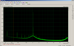
Here is a screen shot I took back in March of this year.
Dick Moore loaned me his EMU0204 and Twin T notch filter to try out while he was on holiday for a couple of months. Okay he's retired so maybe not holiday.
A screen shot of the performance of the SVO at 6Vrms output, 1.072KHz and the multipler. Most of what you see in the spectra is power supply harmonics and some EMU junk. The input to the Twin T is attenuated to 1Vrms (0dBV) and the ARTA is calibrated to 0dBV 1Vrms, The output of the multiplier is at about 64mVrms.
Cheers,
Attachments
AGC for this multiplier.
I still need an AGC for this multiplier. I't has to have a very clean output and as ripple free as possible or what you see in the last post won't be possible.
A THSH would do it but it seems a waist to have a high speed AGC just to have to slow it down again to make it work. This oscillator has no chance of quick settling using lamps so a fast AGC is not needed or will even work. The oscillator settles in less than a second at most frequencies just on the lamp stabilization alone. At higher frequencies it's a bit longer. At low frequencies it's almost instantaneous measured by patients.
What I need is more of an auto level trim but standard servo circuitry tends to fight with the lamps time constant and slows the settling down.
Suggestions? Idea?
Cheers,
Its a great solution. Could you take the servo from the main output and cancel the offset through the system?
The time constant of the thermal device will limit the low frequency performance and harmonic generation. Something with a big filament would be better (heavier) but two full size light bulbs may be a little weird in a box. Thermocouples won't work since they generate DC from the heat instead of a resistance change. I looked at Thermistors which could be valid http://www.digikey.com/Web%20Export/Supplier%20Content/api-technologies-1171/pdf/api-ptc-engineering.pdf?redirected=1 however the note indicates a voltage sensitivity which would be all wrong for this app. This may be the most obscure possible solution for stabilizing http://www.amperite.com/assets/Documents/Ballasts.pdf and they are still made. It looks like they could work pretty well. Now you can have tubes in a all solid state circuit. . .
The time constant of the thermal device will limit the low frequency performance and harmonic generation. Something with a big filament would be better (heavier) but two full size light bulbs may be a little weird in a box. Thermocouples won't work since they generate DC from the heat instead of a resistance change. I looked at Thermistors which could be valid http://www.digikey.com/Web%20Export/Supplier%20Content/api-technologies-1171/pdf/api-ptc-engineering.pdf?redirected=1 however the note indicates a voltage sensitivity which would be all wrong for this app. This may be the most obscure possible solution for stabilizing http://www.amperite.com/assets/Documents/Ballasts.pdf and they are still made. It looks like they could work pretty well. Now you can have tubes in a all solid state circuit. . .
You can't really get $17 each unless what you really want is three copies of the same board 3.8" x 2.5" - the miniboard service is $51 for three boards, the "best" deal they offer for a board anywhere near that size. They've had the same services at about the same pricing for over 12 years now ... here's November 2000 website showing the miniboard service $59 postpaid (to USA only) verses current pricing of $51 + postage: How much ExpressPCB costs - PC board layout editor for Windows. They must be making money at what they're doing. With so many other services available I would have thought they would have dropped their prices.Interestingly enough, but I prefer to do PCB for every project. 33each.com or miniboard service from ExpressPCB ($17 each)
Its a great solution. Could you take the servo from the main output and cancel the offset through the system?
The time constant of the thermal device will limit the low frequency performance and harmonic generation. Something with a big filament would be better (heavier) but two full size light bulbs may be a little weird in a box. Thermocouples won't work since they generate DC from the heat instead of a resistance change. I looked at Thermistors which could be valid http://www.digikey.com/Web%20Export/Supplier%20Content/api-technologies-1171/pdf/api-ptc-engineering.pdf?redirected=1 however the note indicates a voltage sensitivity which would be all wrong for this app. This may be the most obscure possible solution for stabilizing http://www.amperite.com/assets/Documents/Ballasts.pdf and they are still made. It looks like they could work pretty well. Now you can have tubes in a all solid state circuit. . .
Hi Demian,
"Its a great solution. Could you take the servo from the main output and cancel the offset through the system?"
I don't follow what you mean by this. Pictures are worth a thousand words...
What is the main output and what is the system?
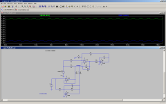
The servo can be returned to different nodes. It doesn't have to be wired through the drivers. An alternative is to return the servo to the non inverting node of the multiplier amplifier. This saves one inverting amplifier to satisfy the phase requirement.
The low frequency problem you mention are not nearly as significant as with traditional lamp
stabilization. The signals in the lamps are tiny by comparison. In fact because of the DC bias on the lamps there is no AC in the lamps at all. There is only a changing DC current and in phase but offset ac voltage across the lamps.
It's an interesting arrangement that lessens the usual problems found with lamp stabilization.
This is a better way to return the servo. The servo decoupling resistor has to be included with and in parallel with R7.
If you mean to include the servo in the AGC there would be no way to balance the lamps as they would both be seeing the same error signal.
Cheers,
Attachments
Last edited:
Here is the basic multiplier design.
I've included a cheesy LTspice schematic and the plot of the lamp's curve.
The 7220 has a cold resistance of about 70 ohms.
Cheers,
This circuit will fit easily onto PCExpress size. Lamps off board, of course. Could use a quad IC as well... at least for proof of concept. Such as OPA1644. -RNM
Last edited:
This circuit will fit easily onto PCExpress size. Lamps off board, of course. Could use a quad IC as well... at least for proof of concept. Such as OPA1644. -RNM
Hi Rick,
Yes the multiplier will fit but I meant the oscillator and multiplier and that won't fit.
The AGC I will put on another board for now until it's all working and then it will all go on one board.
There is also another circuit which goes before the lamp drivers to correct for the non linear VR curve of the lamps.
I didn't include it here because it takes some explanation as to why and how it works and that is an essay of it's own.
Cheers,
Last edited:
I'm sorry about not being clear, what I meant was to sense the dc offset at the main output where the lowest distortion signal is and remove DC offset from there correcting for offset buildup from the cascaded amplifiers.
Hi Demian,
It's not the offset from the amplifier cascade that is a problem. If that's all it was we could just leave it there. The DC off set with no lamp drive is less than a mV and no more the 3mV with drive voltage and the servo correction. With no servo the offset is as much as 300mV. It's not to much to just leave it and block with capacitor coupling but the offset does seem to raise distortion some in the oscillator. I have not been able to measure the distortion of the multiplier at it's normal operating levels. I don't have an oscillator low enough in distortion to measure it. All I can say is the distortion of the multiplier appears to be less than the oscillator itself.
The offset is there because of mismatched lamp VR curve so something has to be done to change the DC voltage across the lamps to match the lamp currents. This can be done in two ways. By offsetting the control voltage to one of the lamps or by applying an offset to one of the multiplier nodes. By applying an offset to the non inverting node the inverting node is forced to match which changes the voltage across one or both of the lamps. Returning the servo to the non inverting node satisfies the phase requirement of the servo saving an inverting stage. We could add an inverting stage and return the servo to the inverting node but this drive the noise and distortion up and it's the same as using the inverting driver stage. The reason I say using the non inverting node is a better arrangement is because there is a bit less noise. We are not passing the servo through a second amplifier. But it does affect the attenuation at the non inverting node. There is some signal returned through the servo and this needs to be taken into account. It will effect the gain AC of the multiplier particularly at low frequency. But this did not seem to be a problem when I tested a 10Hz.
I did try lamps with heaver filaments but the SVO at least did not settle well at all frequencies. The 7220 works right across the bandwidth and within the multiplier gain range.
That's not to say other lamps won't work. It was not practical to try them all and I got tired of growing my stock with parts I'll never use.
By main output do you mean the multiplier output?
Cheers,
I was thinking of removing any residual DC at the main output of the oscillator in the process. For some applications (like precision measurements) the DC at the output causes problems. The vacuum thermocouple, for example, can't tell DC from AC. If one servo could do both it would be nice.
Its a great solution. Could you take the servo from the main output and cancel the offset through the system?
The time constant of the thermal device will limit the low frequency performance and harmonic generation. Something with a big filament would be better (heavier) but two full size light bulbs may be a little weird in a box. Thermocouples won't work since they generate DC from the heat instead of a resistance change. I looked at Thermistors which could be valid http://www.digikey.com/Web%20Export/Supplier%20Content/api-technologies-1171/pdf/api-ptc-engineering.pdf?redirected=1 however the note indicates a voltage sensitivity which would be all wrong for this app. This may be the most obscure possible solution for stabilizing http://www.amperite.com/assets/Documents/Ballasts.pdf and they are still made. It looks like they could work pretty well. Now you can have tubes in a all solid state circuit. . .
These current ballasts look very interesting. I wonder what there distortion characteristic are like?
You can't really get $17 each unless what you really want is three copies of the same board 3.8" x 2.5" - the miniboard service is $51 for three boards, the "best" deal they offer for a board anywhere near that size. They've had the same services at about the same pricing for over 12 years now ... here's November 2000 website showing the miniboard service $59 postpaid (to USA only) verses current pricing of $51 + postage: How much ExpressPCB costs - PC board layout editor for Windows. They must be making money at what they're doing. With so many other services available I would have thought they would have dropped their prices.
Please point me to a cheaper service. They do add soldermask etc. for not that much more. Mind you I have no interest in buying a high end CAD program or managing drill layers etc. I tried EAGLE and it was not for me.
Last edited:
I was thinking of removing any residual DC at the main output of the oscillator in the process. For some applications (like precision measurements) the DC at the output causes problems. The vacuum thermocouple, for example, can't tell DC from AC. If one servo could do both it would be nice.
I see. Well I'm concerned for the offset in the multiplier because I believe this is where the rise in distortion originated at. Not sure about using a servo on the oscillator it self. Servos introduce a TC and this might upset the oscillator. It could also upset the AGC. But we can investigate the effect of offset in an oscillator by introducing some and see what happens.
Some of the theories around oscillators are very old and where valid for the kinds of circuits being used at the time. I think we should retest these theories and not just accept them as valid. Offset in a single discrete amplifier oscillator may be different than ones build with op amps. How much offset?
"For some applications (like precision measurements) the DC at the output causes problems."
Maybe the best place to address this would be right at the output. Like if a buffer or output amplifier stage is used then deal with the offset there. I like to avoid series blocking capacitance if at all possible so servos are attractive. But then again a nice floating balance output eliminates the offset problem.
Hi Scott,
What doesn't work with one oscillator type might work with another.
I have a multiplier along the lines of what Demian is suggesting. It doesn't work with a Bridged T but it works perfectly with a SVO. It doesn't work with a fast ALC because the tau of the lamp is too long. It doesn't respond fast enough. It is capable of stabilizing the SVO on it's own. All it really needs is an auto set level sort of thing. Some thing to just bring the level to a dc reference slowly but not so slow it is annoying.
Can you share some part numbers for these plentiful thermal RMS detectors?
Cheers,
Why does it have to be thermal RMS why not log computing? I forgot to mention that that was what I made, I epoxied a power resistor to the 3300ppm Tellabs resistor and put it in a styrofoam isolation surround. When it finally locked in I got -130dB or so.
Please point me to a cheaper service. They do add soldermask etc. for not that much more. Mind you I have no interest in buying a high end CAD program or managing drill layers etc. I tried EAGLE and it was not for me.
I use Diptrace myself. A non profit license is not much. I didn't like Eagle either.
I use Diptrace myself. A non profit license is not much. I didn't like Eagle either.
Thank's
As for RMS in this application neither the BW or dynamic range is an issue so something like an AD637 should work just fine. I found a huge stash in my junk bin (nice gold DIP's) if you want a couple.
- Home
- Design & Build
- Equipment & Tools
- Low-distortion Audio-range Oscillator