What would happen using another opamp in series with the oscillator opamp in such a way that it is one super high OLG opamp -- would the thd be even lower? Thx-RNMarsh
Composite amplifiers are possible but are usually composed from two different type amplifiers. Voltage feedback + current feedback for example.
The LT supper oscillator is a tuned composite amplifier to make it work at 10KHz.
Generally the compensation of two amplifiers in series raps the phase around through 180 deg and beyond before reaching unity. So they are unstable. We would like to see a slowing down of the rate of change of phase rather than an speed up. If the slope increases so does the rate of change of phase. Second order compensation networks can be made to work which provide extended bandwidth.
But what makes you think this is the cause of limit?
Last edited:
there are two places to reduce distortion in the oscillator circuit (neglecting passive parts, contacts etc):
The opamp and the jFET. I replaced the jFET with a mulit-turn control trim pot; I could tune the distortion to under .001% THD+N. I ran out of control sensitivity and need a smaller R value with 28 turns to fine tune it further. I used a 100 ohm trim pot. With the jFET out of the picture, THD changes with opamp's can be learned.
Happy Holidays, Everyone !! Take care of your health is the best present you can give. Thx -RNMarsh
Last edited:
QuantAsylum was talking first release of software in the next few weeks but I don't know about the Hardware.
You can Email support at QuantaSylum and ask.
support@quantasylum.com
Cheers,
Thanks, I have send them a mail.
May I ask why you are buying a E-MU 0204?
Best regards,
Mogens
The box is ideally suited to mobile electronics but needs external stuff for traditional audio. I am working on a solution for my needs.
Hi Demian,
I realize you wrote "for my needs", but is it something you would share in case it's not to specialized for your needs?
I assume it might be some attenuator and filter front end?
Best regards,
Mogens
Thanks, I have send them a mail.
May I ask why you are buying a E-MU 0204?
Best regards,
Mogens
Hi Mogens,
This is a beta program with the QA400. I need something to compare to.
The EMU0204 and ARTA is something I am familiar with and I know what the base line is.
The QA400 in the end will be the better of the two but it not quite there yet.
In addition to Demian's comment. I believe QuantAsylum is working on a front end solution of their own.
It's been mentioned to them often enough. They have a specific target for this product and that is fine.
For now all anyone really needs to get going is a Twin T or other notch and an attenuator at the input to the notch which can be as simple as a wire wound pot. For smaller signals some amplification might be necessary but not essential. For other needs you might want a balanced input converted to single by shorting one input. Some filtering would be nice but that would only make the FFT look better and define a smaller bandwidth.
I would like galvanic isolation myself.
All these things are difficult to do with out adding to the baseline. Add-on's are probably the way to go. Then we are not stuck with one or two confuguarations.
Cheers
Last edited:
QA400
This is a great combination of hardware and software. It does what its intended to do. There are still some bugs in the calculations of levels etc, They are actively working on them.
It has two real limitations. First comes from not acting like an audio interface so other software doesn't work with it. For now all you get is the software they have created. Second, the input/output levels are what I would call mobile electronics levels; 1V max.
I am drafting an expresspcb circuit/layout to address this. First differential inputs, then differential attenuator to handle up to 100V rms and finally an active balanced ground adaptive output with up to 10V single ended/balanced out. Since the QA400 has a common ground for the 4 i/o's, differential connections are essential. Then getting accurate calibrate-able levels throughout is important.
Both of these are more complex than they appear,
It is conceivable that this could be powered from USB but I'm not sure yet. I need to find a good source for 5V to +/- 18 v dc-dc converters that are not real expensive. It may be possible to use a charge pump. However the grounding issues may make that impossible.
I'll post my work in progress later. . .
Hi,
Thank you both for your detailed answers.
It would be great if this thread could come to include a design for a front-end to the QA400 that would make it easy to perform comparative measurements. Perhaps this could even become a diyaudio standard.
I have a 1 and 10 KHz version of Victors oscillator, together with a @juli and a E-MU tracker Pre, which I believe is somewhat similar to the E-MU 0204. But, I haven't got around making any notch and front-end.
I'm sure you know Glen's project: An Audio T.H.D. Analyser
I have been speculating if his measurement front-end and filter could be simplified somewhat and adapted to match the soundcard interface. I this case it could be the QA400. Perhaps it's more complex than it actually needs to be.
Best regards,
Mogens
It is conceivable that this could be powered from USB but I'm not sure yet. I need to find a good source for 5V to +/- 18 v dc-dc converters that are not real expensive. It may be possible to use a charge pump. However the grounding issues may make that impossible.
Some folks who built Millet's RMS converter experienced noise issues with USB.
If I had to design a piece of audio instrumentation communicating via USB I'd isolate it (Analog Devices has a development kit for around $50, which you can do for a fraction if you SMT, same with other folks), and use a linear supply on the business end.
Hi jakinnj,
Dick Moore bought one of those AD demo boards but couldn't use it because it only does full speed. The EMU0204 and QA400 use high speed.
If we could interface to ethernet and back we'd have the galvanic isolation. or maybe something else
balanced.
Cheers,
Some folks who built Millet's RMS converter experienced noise issues with USB.
If I had to design a piece of audio instrumentation communicating via USB I'd isolate it (Analog Devices has a development kit for around $50, which you can do for a fraction if you SMT, same with other folks), and use a linear supply on the business end.
Hi jakinnj,
Dick Moore bought one of those AD demo boards but couldn't use it because it only does full speed. The EMU0204 and QA400 use high speed.
If we could interface to ethernet and back we have the galvanic isolation or something else
balanced.
Cheers,
QA400 interface
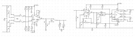
Here is a sketch of what I'm working out. Its missing gain calibrations, common mode trims, output protection etc. It will give the general idea however. I'm using the THAT parts because they have a pretty high level of integration and take care of a bunch of precision resistors. I don't know yet if they will limit either the noise or distortion. Alternatives would be very interesting to look at. These are also available in DIP packages making them easier to deal with and, if socketed, easier to recover after mistakes.
Input protection uses small fuses (.062A fast blow). I may be able to simplify the output amp if the QA400 can drive a lower Z load without degradation. The opamp is a placeholder. Not figured out yet is power supply and possibly a local reference oscillator (1 KHz, light bulb stabilized, lockable from the QA400).
Attachments
Here is a sketch of what I'm working out. I don't know yet if they will limit either the noise or distortion. Alternatives would be very interesting to look at.
That is a pretty important issue -- the front end interface adding to the measured DUT distortion. -RNM
His whole analyzer looks well thought out. I'm thinking of getting just the oscillator part to check out. -RNMarsh
The THAT parts were suggested to me by Bill Whitlock of Jensen transformers. He said they would be a good option for the AP input stage. Until I get my hands on something I can't tell on way or the other. I suspect that for most audio work they will be more than good enough. The cluster of parts to do it with other circuitry gets huge. The similar input board for the Boonton is 4" X 12" with not much vacant real estate. Paralleling opamps to lower noise can work. On a Yamaha tuner I have they paralleled (without balancing resistors!!) two opamps on the same die and got a real 3 dB improvement. I don't know if that would work here. The biggest constraint is the input attenuator impedance. 10K for 100V RMS is 1W, which has impact both in the source loading and in the size of the components. Going smaller would not be an option I think. The industry standard is actually 100K.
The THAT parts were suggested to me by Bill Whitlock of Jensen transformers. He said they would be a good option for the AP input stage. Until I get my hands on something I can't tell on way or the other. I suspect that for most audio work they will be more than good enough. The cluster of parts to do it with other circuitry gets huge. The similar input board for the Boonton is 4" X 12" with not much vacant real estate. Paralleling opamps to lower noise can work. On a Yamaha tuner I have they paralleled (without balancing resistors!!) two opamps on the same die and got a real 3 dB improvement. I don't know if that would work here. The biggest constraint is the input attenuator impedance. 10K for 100V RMS is 1W, which has impact both in the source loading and in the size of the components. Going smaller would not be an option I think. The industry standard is actually 100K.
Hi Demian,
All the resistor in the 339a input attenuator are 2 - 3 watts. The 339a input has to be able to blow the fuse with 300V without the resistor catching fire. I would think as an added bonus the resistors in that size would be more thermally stable because of the extra mass.
The LT supper oscillator is a tuned composite amplifier to make it work at 10 kHz. Generally the compensation of two amplifiers in series raps the phase around through 180 deg and beyond before reaching unity. So they are unstable.
To satisfy stability requirements, we need >0° phase margin at the unity loop gain frequency only. At frequencies where loop gain is large, phase margin can be what it wants, even negative.
The LT "super oscillator" doesn't oscillate because the opamps are unstable. It oscillates for the same reason as every RC oscillator oscillates--for the tuned feedback network.
Note that for low distortion the open-loop gain of the opamp needs to be high at the frequencies of the harmonics, not at that of the fundamental.
Samuel
Adding to Samuels post, have a look here : www.ti.com/lit/an/sboa015/sboa015.pdf , a very good app note by Burr Brown "mastermind" Jerald G. Graeme.
There comes a heading somewhere "Phase only matters at the intercept" which took me quite some time to understand and accept. Like many, I've always thought not dipping below 45deg phase margin at all frequences of the OLG is a criterion for stability but it's not, more like only when you need the opamp/composite be stable at any arbitrary gain setup which is flat at the intercept OLG point. For a fixed gain design, though, the phase can dip down to any value as long as it comes back and hits the OLG with its phase no more than ~120° behind the OLG phase (for a ~60deg PM)
I then actually built -- deadbug style -- a variant of his circuit of fig.9, low gain inverting with noise-gain comp (50dB), using two 5534's with 33pF comp each. OLG (EDIT: No, Loop Gain) Phase now certainly must have crossed though 180deg at two points somewhere below intercept, given the additional pole from the noise-gain comp. No sign of instability was seen and the distortion performance was really good. Overload recovery was nasty, though...
Last edited:
There comes a heading somewhere "Phase only matters at the intercept" which took me quite some time to understand and accept. Like many, I've always thought not dipping below 45deg phase margin at all frequences of the OLG is a criterion for stability
Christophe Basso explains how to think about loop stability: http://cbasso.pagesperso-orange.fr/Downloads/Papers/Phase margin and quality factor.pdf
To satisfy stability requirements, we need >0° phase margin at the unity loop gain frequency only. At frequencies where loop gain is large, phase margin can be what it wants, even negative.
The LT "super oscillator" doesn't oscillate because the opamps are unstable. It oscillates for the same reason as every RC oscillator oscillates--for the tuned feedback network.
Note that for low distortion the open-loop gain of the opamp needs to be high at the frequencies of the harmonics, not at that of the fundamental.
Samuel
I wasn't suggesting that the op amp must be unstable to oscillate. I meant D.E. tuned the the sections to manipulate the GM and PM. He did illustrate this in his write up on the oscillator.
Well yes it makes sense that we only need high feedback gain at harmonics. If we consider a network like a bridged T, a passive notch network placed inside a negative feedback loop creates a band pass filter at a very high Q. There is little to no negative feedback at resonance since this is a high impedance state therefore we have open loop gain at Fr. What ever that is at a particular Fr.
Then it stands to reason if we use a second amplifier to provide some positive feedback to the tuned network to sharpen up the shoulders, we should see better 2nd and perhaps 3rd H results. We can do this with a Twin T notch network or a bridged T. This maybe an improvement to the single amplifier oscillator. If we pull up some 9dB at 2nd and 4db at 3rd or what ever it may be. This might be easier to do than tackling a composite arrangement. Is it more gain that we need for better distortion performance or just better use of it?
It also stands to reason then that 'high Q networks provide lower distortion' is a myth.
The lower Q networks provide more negative feedback in and around the fundamental. So there is no concern for the loss of Q by sharpening the shoulders of a network by whatever means. It just adds to the complexity.
I will read these articles mentioned. Composite amplifiers are one thing I've haven't had much success with stabilizing.
Cheers,
- Home
- Design & Build
- Equipment & Tools
- Low-distortion Audio-range Oscillator