The 339A is beginning to see the effects of the THD of the opamps used in itself and also the parts and even contacts of the switches. All issues which an audio amp builder would also come to address at these levels of harmonics. The performance will be limited by the parts we use. I am installing sockets everywhere to try different opamps in different places.... will be much easier until the parts are settled as to which are best ones and stable. Thx-RNMarsh
I have the 1468 working fine in the input stage and an LME49710 in the buffer stage. This brought the noise way down on the FFT from the output of the notch filter. We have a max gain of 30dB in the input stage and need a GBP of at least 25MHz. At 30dB gain the LT1468 is 25MHz.
I may have to deal with some RF noise from the oscillator. When the range switch is set to off, which puts a 600 ohm load on the analyzer input, the meter goes to near zero with a -80dBV range. It is garbage getting in. We can filter the output of the the oscillator no problem.
Cheers,
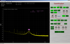
Input and buffer amp
Here is the result for replacing the input amplifier with a LT1468 and the buffer with an LME49710. All the hash seen in prior plot is near gone and what remains is power supply harmonics and oscillator distortion.
All the caps found parallel the resistors in the input amplifier gain range stage have to be removed. The LT1468 doesn't like this. I'll work on filtering the input but for this I have to
do a frequency and level sweep.
Attachments
How much further do we have to go before hitting quantum noise? 
I'm not surprised seeing how formerly passive parts are becoming measurable contributors to residual distortion and noise, to say nothing of ambient RFI and increasingly critical layout of parts and grounding to achieve better results at this low level. The CFLs in my work room are becoming an annoyance--the lamps directly radiate stuff around 40KHz and above.
I'm trying to build a copy of the Cordell SV oscillator, using good metal film resistors and even a few bulk metal foil resistors (I have about 90 2K0000 RNC90Ys if anyone's interested--I'll give away free samples). I'd use more foil resistors and 25 ppm or better metal films if I could afford them. And a Nichicon 220 uF bipolar cap for output coupling.
I'm kind of hoping to demonstrate qualification of passive parts using ultra low distortion measurement, a poor man's Radiometer CLT-1 or the Danbridge equivalent:
Danbridge
Last edited:
I think you will find that getting the CLT-1 distortion level will be really difficult. The CLT-1 has a low distortion oscillator and a power amp set up to drive a complex filter network to get everything above the second harmonic to -160 dB under load. And then a narrow band filter to see how much HD3 is still present.
After all of that most good parts are at the residual of the instrument. Pots are not. Cheap parts maybe not. The bulk foil parts and wirewound resistors are at the residual as are good metal film resistors. LDR's are not even near the residual but you can see the nonlinearity of those with a conventional analyzer. Looking at the esr of an electrolytic cap may be interesting. I should try that. However at 50 milliohms we will be below the range of one of these things. I should get an assortment of film caps from Richard Marsh to look at and see if there are significant variations to learn from.
After all of that most good parts are at the residual of the instrument. Pots are not. Cheap parts maybe not. The bulk foil parts and wirewound resistors are at the residual as are good metal film resistors. LDR's are not even near the residual but you can see the nonlinearity of those with a conventional analyzer. Looking at the esr of an electrolytic cap may be interesting. I should try that. However at 50 milliohms we will be below the range of one of these things. I should get an assortment of film caps from Richard Marsh to look at and see if there are significant variations to learn from.
How much further do we have to go before hitting quantum noise?
I'm not surprised seeing how formerly passive parts are becoming measurable contributors to residual distortion and noise, to say nothing of ambient RFI and increasingly critical layout of parts and grounding to achieve better results at this low level. The CFLs in my work room are becoming an annoyance--the lamps directly radiate stuff around 40KHz and above.
I'm trying to build a copy of the Cordell SV oscillator, using good metal film resistors and even a few bulk metal foil resistors (I have about 90 2K0000 RNC90Ys if anyone's interested--I'll give away free samples). I'd use more foil resistors and 25 ppm or better metal films if I could afford them. And a Nichicon 220 uF bipolar cap for output coupling.
I'm kind of hoping to demonstrate qualification of passive parts using ultra low distortion measurement, a poor man's Radiometer CLT-1 or the Danbridge equivalent:
Danbridge
Hi Damon,
It's a particularly bad time of year for RFI where I am. For some reason the intensity RF propagation is greater in the very cold and dry. Where I am it was -31C, -24F last night.
A while back I was setting up a comparator for a zero crossing detector and found a 14.25MHz ringing that just wouldn't go away. I thought it was my circuit. It turned out the Cisco cable modem sitting beside me is emitting a burst signal at that frequency. I measured 30mVpp on the oscope holding the probe about 18" from the modem. In RF terms that's about 29.5 dBmV. If a cable TV system had a leak that strong on an aeronautical frequency they would be given 24 hours to fix it or risk loosing those channels.
In contrast to when the 339a and others where designed consider the difference in the amount of RFI from then to today.
I had to add a large amount of hysteresis to my zero crossing detector to tolerate the environment and that changed my trigger point. Can't win.
Cheers,
Last edited:
I think you will find that getting the CLT-1 distortion level will be really difficult. The CLT-1 has a low distortion oscillator and a power amp set up to drive a complex filter network to get everything above the second harmonic to -160 dB under load. And then a narrow band filter to see how much HD3 is still present.
After all of that most good parts are at the residual of the instrument. Pots are not. Cheap parts maybe not. The bulk foil parts and wirewound resistors are at the residual as are good metal film resistors. LDR's are not even near the residual but you can see the nonlinearity of those with a conventional analyzer. Looking at the esr of an electrolytic cap may be interesting. I should try that. However at 50 milliohms we will be below the range of one of these things. I should get an assortment of film caps from Richard Marsh to look at and see if there are significant variations to learn from.
I don't doubt it will be a challenge, but fun trying.
Reading the application notes on the CLT-10/20, I see that very low resistor Tc corresponds with lowest distortion, as should low voltage coefficient. Good wirewound resistors were virtually unmeasurable, as I'm sure bulk foil resistors are. Apparently it can measure down to -170db or so--impressive!
That must be >some< power amplifier used to drive the test components at 10 KHz.
Gives me a bit of perspective, and perhaps a means for testing my collection of less-premium components just to be sure they're still good. Defects in end caps and other quality issues apparently stand out. I would imagine old carbon track potentiometers are real stinkers.
Going to test my limited collection (may have to rob other projects) of opamps on a simple Wein bridge breadboard before I power up the oscillator. With a AD797, bulk foil resistors and polystyrene caps, I hit my Tek AA501A's residual of .001%, but most of them are 5534s or slightly better. I'm a little surprised the original SV design did so well with the available opamps of the time.
And a Nichicon 220 uF bipolar cap for output coupling.
Try the Elna Silk caps as well (2, back to back)-- I ran some distortion tests and these did best.
With respect to the CFL's -- "Abandon hope all ye who enter here..."
1audio;3277457 After all of that most good parts are at the residual of the instrument. Pots are not. Cheap parts maybe not. The bulk foil parts and wirewound resistors are at the residual as are good metal film resistors. LDR's are not even near the residual but you can see the nonlinearity of those with a conventional analyzer. Looking at the esr of an electrolytic cap may be interesting. I should try that. However at 50 milliohms we will be below the range of one of these things. I should get an assortment of film caps from Richard Marsh to look at and see if there are significant variations to learn from.[/QUOTE said:Check with Brian Elliot.. I think he still lives in Stanford area. he did origianl reserach into distortion limits/mechanisms for IBM... then when he retired from IBM, went back to Stanford and worked for HP for awhile (PHD EE Stanford). He did capacitor tests using a bridge setup and found some interesting things... one I think was that on some film caps the thd/harmonics went up with DC bias on them. The MultiCap was best brand he measured. Dont have to duplicate tests if someone else has already done them, is my thinking. Thx-RNMarsh
Here is the result for replacing the input amplifier with a LT1468 and the buffer with an LME49710. All the hash seen in prior plot is near gone and what remains is power supply harmonics and oscillator distortion.
All the caps found parallel the resistors in the input amplifier gain range stage have to be removed. The LT1468 doesn't like this. I'll work on filtering the input but for this I have to
do a frequency and level sweep.
Now, what does the meter on the 339A indicate? Is it off the zero position? Dropped in several op-amps today (LT1468's). I think I may need another FFT to verify this thing is even turned on and working !! Thx-RNMarsh
Last edited:
Now, what does the meter on the 339A indicate? Is it off the zero position? Dropped in several op-amps today (LT1468's). I think I may need another FFT to verify this thing is even turned on and working !! Thx-RNMarsh
I take it your results are good?
Cheers,


Greening the HP339A -
One can get excellent results by starting with parts upgrades to an HP339A; trim pots and electrolytic. Then Opamps. I only used the LT1468 types which are internally compensated. The IC thd is plenty low (>-120db spec) and I dont want to mess with wide band, unstable IC's used in a layout designed for 100KHz.... even if their thd is even lower. Contacts are a problem still... the old brass contacts do not wear well with time and the tarnish isnt nice to thd. Clean them and keep them clean. Will add the new buffer IC when it arrives. Thx-RNMarsh
One can get excellent results by starting with parts upgrades to an HP339A; trim pots and electrolytic. Then Opamps. I only used the LT1468 types which are internally compensated. The IC thd is plenty low (>-120db spec) and I dont want to mess with wide band, unstable IC's used in a layout designed for 100KHz.... even if their thd is even lower. Contacts are a problem still... the old brass contacts do not wear well with time and the tarnish isnt nice to thd. Clean them and keep them clean. Will add the new buffer IC when it arrives. Thx-RNMarsh
Last edited:
Check with Brian Elliot.. I think he still lives in Stanford area. he did origianl reserach into distortion limits/mechanisms for IBM... then when he retired from IBM, went back to Stanford and worked for HP for awhile (PHD EE Stanford). He did capacitor tests using a bridge setup and found some interesting things... one I think was that on some film caps the thd/harmonics went up with DC bias on them. The MultiCap was best brand he measured. Dont have to duplicate tests if someone else has already done them, is my thinking. Thx-RNMarsh
Hi Richard,
As I recall, when Bateman did his testing different pots had different distortion levels.
Cermet being the worst but some conductive plastics had distortion levels of 0.000x
Sorceress and Demian--> You are both correct: Use conductive platsic when you can. A bargain used to be that some pots sold by Radio Shack were made by Alps and Brian Elliot said they were unmeasureable in thd. It wasnt conductive plastic, though. I used one I had in my parts stash on my headphone amp input.
Those tests did not put DC thru the pot at the same time they are tested with ac.
However, to get the fine pointed, deep null trim I needed to use a multi-turn pot.... I used a 28-turn cermet. In this application the cermet worked well and did not increase distortion to where it would be noticable ---- things were more limited by other parts/issues... [dont know brand/source/quality I used.] When not able to measure, then use conductive plastic, generally, as first choice. Thx-RNMarsh
Last edited:
Pot
Okay so where are you all getting your pots from? I'm kind of stuck with Digikey and Newark as second. Everything is mail order where I am. I spend almost as much in shipping as I do in parts. I Tend to make big orders because of this. Digikey had one pot that will work for the oscillator level control that's under $65.00 and I think it is cermet. I don't like the wire wound because of the natural detent. I can never get the level quite on.
Cheers,
David.
WW have the lowest noise. Inductance shouldn't be an issue.
More 339a mods
It just keeps getting better. I've done some gain redistribution in the 339a and the result is,
well, a quantum leap.
The total attenuation and total gain through the signal chain is 80dB and this is spread throughout the stages. I mentioned before the intent to attenuate the buffer input by 10dB to normalize the output of the notch amplifier to the FS of the QA400 software. This left the analyzer 10dB short so I made up for it by adding 10dB to the x100 meter amplifier. Not only did the noise floor drop but so did the distortion. With a well tuned notch the meter dropped from the 339a residual of 0.0015% to 0.0005%.
I'm going to do more gain redistribution throughout the analyzer because with lower signal at the input amp, buffer, notch filter etc. both the noise from ingress and THD is lower. The meter amp doesn't seem to mind the extra gain. I may change this amplifier to the 1468 for extra bandwidth and lower noise. The 1468 is stable at high gains without any further compensation.
Another issue is with maintaining the notch depth. As it is the it works at the level it calibrated for but loses the depth at other levels. Taking the signal straight off the notch filter doesn't offer constant level. But we have constant level off the auto set level for sure. I going to try routing the signal from here to the input of the balance modulator. I think this should work as long as there isn't a change of phase at this point with all the variables.
If we can move most of the gain to the meter amp without losing bandwidth, I think the results will be even better than what I have now. If we could put all of the 80dB at the meter amp then all we have in the rest of the signal chain is attenuation. The only thing we have to respect is the minimum level into the RMS convertor.
I will report on the effect of both the gain redistribution and routing of the modulator input.
Cheers,
Last edited:
When will I be able to get a QA400 like you have? My FFT works but isnt practical to lug around an old heavy HP FFT bench analyzer to monitor residuals. I know there are other FFT (ARTA/ADC-DAC) but the one you use offers some good and useful features.
Looking forward to more changes for the better. And to think, you were about to throw in the towel on this 'boat anchor'. Thx-RNMarsh
Looking forward to more changes for the better. And to think, you were about to throw in the towel on this 'boat anchor'. Thx-RNMarsh
Last edited:
When will I be able to get a QA400 like you have? My FFT works but isnt practical to lug around an old heavy HP FFT bench analyzer to monitor residuals. I know there are other FFT (ARTA/ADC-DAC) but the one you use offers some good and useful features.
Looking forward to more changes for the better. And to think, you were about to throw in the towel on this 'boat anchor'. Thx-RNMarsh
It's still a boat anchor.
Cheers,
- Home
- Design & Build
- Equipment & Tools
- Low-distortion Audio-range Oscillator