How fast does the QA400 update? I find with my old Wavetek FFT its slow enough to be quite frustrating. The PC is across the room so I don't use it too often for this stuff.
How do I find out more about the QA400? Will they talk to me?
Hi Demian,
Just got to there web pages.
QA Blog - QuantAsylum Home Page
If you want to talk to some one just email
QuantAsylum Support <support@quantasylum.com>
And yes they will talk to you. it's in there interest.
They are a fairly new company and not stuffy at all.
The QA400 uses a different software and hardware technology. It doesn't use Windows streaming API calls to handle the data. The data is sent in packets much like ethernet.
The reason for this is to enable error checking of the packet. The sampler even has a packet drop LED indicator to let you know if a packet has been dropped.
Windows API doesn't do error checking it just sends a stream.
However there is no escaping Windows API's and XP has known latencies which won't be fixed by Microsoft. It was for this reason ASIO was written to bypass the Windows API layer. Unfortunately with XP there is still some delay. In the lower resolutions it's near real time but at 32768pts there is delay. It's not the fault of the SW or HD, the HD is FPGA controlled.
I'm told by QuantAsylum the latencies are cleaned up in Win7 or above and it is their aim for real time. I don't have Win7 because it's a pita to do with no upgrade and we have to pay more for XP compatibility. I'm told there is a place in the QA400 config file for optimizing timing with XP. I have a Intel I5, 2500 so XP latency is intentionally set.
QuantAsylum is leaning towards the Asian manufactures, the professional and hobbyist alike. The support will be ongoing. The QA400 is geared for audio analysis. It is not a sound card- software combo but it is priced compatibly. The software and hardware are married. There are no Windows drivers using standard Windows audio functions.
These inexpensive approach with FFT spectrum analysis today have almost surpassed all the old hardware. It's not so painful as it was through the 90's and maybe the 00's
I'm old enough to have gone through DOS and Windows right from the beginning and I guess I'm one of those people who thinks Microsoft owes me a stable operating system for free for what they put us through. The Icons on DIY don't work for me so 'smiley face'.
Seriously though it's just a pain in the butt to upgrade.
Cheers,
Being able to have a wide range of test freq is a nice convenience. I have all the IC's on hand now that you used so far but waiting to see what else.....
So far the complete HP339A system -- reading its own oscillator at almost stock (osc + analyzer distortion) - with just a tune up and changing the two null trimmers (using a 3580A spect analyzer on the output monitor port of the 339A) -- gives a noise floor of -145. The H2 is -105 and the H3 -130. Its a good beginnng and its getting better!Thx-RNMarsh
Hi Rick,
Do you prefer Rick or Richard?
"gives a noise floor of -145" This would have to be a calculated noise floor measuring on the monitor output. With the gains in the 339a a noise floor of -145 is not possible with direct reading. If so something is wrong.
Each 339a has it own characteristics it seems. Some are in better shape than others.
Yous sounds like it is great shape.
My aim here is to do these mods with as little impact on the original as possible.
However I might break the rule a bit with the input upgrades to new op amps that don't require the compensation components. What ever I do though is completely reversible.
I don't like to hack. But the coupling between the input buffer and notch filter is directly connected I think. For this to work 10dB attenuation needs to be added.
Cheers,
339a with input circuit connected
This is with the input amp and buffer amp reconnected.
I increased the input attenuation by 10dB to match what I had before into the notch filter.
What the notch filter is seeing is 1Vrms @ 1KHz same as before.
The Analyzer is reading about 0.0015% THD+N with all the filter in.
With the filter out it reads .08% and with only the 400Hz out it reads .0018%.
Evidently I have a big noise problems with this 339a. The wide band RMS meter measures the entire band width of distortion and noise to-3dB but continues to measure far out beyond this and if there is peaking or parasitic oscillation going on some where.....
I have noted parasitic oscillation in the lower sensitivity range setting with certain ground connections. I can't use my HP2581C connected to the monitor out without a low level rf parasitic. It doesn't take much to set the 339a analyzer off this way. There is a reason why HP put wide band rf series chokes on just about all the inputs and outputs. I've had problems with these chokes causing small resonance and triggering rf parasitic oscillation in another oscillator connected to the analyzer input. These are things to watch out for and can artificially raise a distortion measurement or level for that matter. I spent two days trying to trace an oscillation that turned out to be a grounding problem. Won't get followed again.
This looks pretty good. You can see a slight rise in distortion. I don't know if this is enough to justify further input circuit mods other than changing the scale. I'll leave that up to the individual but I may try it for myself.
There is at a least a couple of approaches to changing the scale. I can change the gain of the input amplifier by changing the value of one resistor, but this will through the scale off for the entire unit including the level meter which works very well. One could install a switch somewhere to switch between scales. The other option is to attenuate the signal into the notch filter buffer which bypasses the level meter mode. This however will require surgery on the PCB and I hate hacking. A third option is to make up a daughter board which solders into the socket space of the buffer amp, but this is a lot of fuss.
I would like some input on this. The only area I'm okay with cutting is the AM input.
Rick you will need some breakout boards for the OPA1641 if you use them. What I'm using is the ones from Sparksfun 8 pin SOIC to DIP. Then using an IC socket, the ones with the solid nickle plated pins and sockets. Stick 20 gage solid wire through the breakout board holes into the IC sockets and solder them in. This gives a riser which you will need to clear some of the parts on the 339a board and makes for a very nice solid connection.
Breakout boards other then Sparksfun should work just as well.
Cheers,
Attachments
Last edited:
The numbers - how to mods
My numbers are also with all filters In. Its pretty useless with the filters out.... just measuring noise. And, I did take care to configure my external grounds/coax to eliminate ground induced hum components to a min.... floated the external scope and analyzer from ac ground and the like.
The noise floor (-145) and harmonic levels are from the FFT analyzer looking at the monitor output.... not a direct measure from the monitor output with a wideband rms voltmeter.
I am willing to make ANY mod.... cutting traces is no problem, niether is replacing a whole pcb or any part of it. I'm not a novice and wouldnt recommend a novice do this sort of thing on a sophisicated piece of test equipment. However, there are a lot of used 339A out there at affordable costs so some others might try some or all of the upgrades/mods and maybe another would do it for others for a fee. Two parts -- the oscillator upgrade and the analyzer upgrade.
Thank you for your time and effort... we all appreciate it. -RNMarsh (Rich, Richy, Dick, Richard. Marshy? But, I get confused when other people are also called Richard in the forums I watch/comment. Maybe RM, like I use JC or SW for others. )
Last edited:
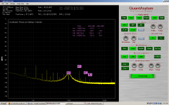
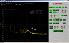
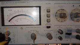
Monitor view
Here is a look at the monitor view after all that's been done.
We can see the scale is about right with a bit of added hash higher up.
The noise floor is near scale as well. So the distortion is confined to the input and notch filter.
One thing that occurred to me is with positive feed back in the notch filter the shoulders are less attenuated with the notch. Further more the notch deep is traded off for band pass flatness. But with the added distortion maybe we can afford more band attenuation from the notch filter. This would correct for residuals and deepen the notch and shoulders at the same time. The amount of feedback is then just a calibrated measure. We would need to precisely know the harmonic levels of the source and this might just be a matter of carefully injected level at the harmonic frequencies. One nice thin about the 600 ohm arrangement is a second oscillator can be easily added.
Cheers,
Attachments
Looking through my collection the Amber 3501 (manual here: http://www.richardhess.com/manuals/Amber3501.pdf has a very interesting VCA/AGC circuit used in both the oscillator and amplifier. It uses an opamp and a quad transistor. In the oscillator there is a second harmonic trim that could possibly be borrowed. It takes input from two phases of the oscillator and mixes it back to "null" the second harmonic. (Sheet 7 of the schematic). In the analyzer (Sheet 9) they have two trims for the frequency AGC (V2003 and V2004) that help linearize it. Nothing for the amplitude control that uses an LDR.
The 3501 I have that has not been tweaked in forever seems to work pretty much to spec (down to .0006% THD). I'm waiting for a power supply and battery to get it back up and running properly. It will be interesting to see how good it actually is when fully calibrated.
The 3501 I have that has not been tweaked in forever seems to work pretty much to spec (down to .0006% THD). I'm waiting for a power supply and battery to get it back up and running properly. It will be interesting to see how good it actually is when fully calibrated.
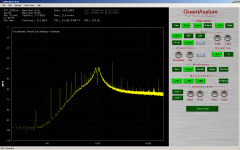
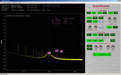
No positive feedback
This is with no positive feedback on the notch filter.
Notice there are no shoulders about the notch but the harmonics are attenuated too much.
Too bad we can't have our pie and eat it as too.
But maybe there is a happy medium. That will require injecting level at the harmonics.
A amount of fundamental must be present for the auto tune to lock onto but at this attenuation I don't think a calculation is necessary if the injected signal is large enough.
More investigation is necessary.
Cheers,
Attachments
Hi Demian,
The QA400 uses a different software and hardware technology. It doesn't use Windows streaming API calls to handle the data. The data is sent in packets much like ethernet.
The reason for this is to enable error checking of the packet. The sampler even has a packet drop LED indicator to let you know if a packet has been dropped.
Windows API doesn't do error checking it just sends a stream.
Cheers,
Not sure you're answering Demians question, the CPU load for an FFT has very little to do with the audio hardware. At 96K sampling it takes approximately 1/3 of a second to load 32k points by definition it can not be done any faster, with modern CPU's you could probably do several 100 32K point FFT's in that time. Check out the FFTW benchmarks at MIT. For all practical purposes the compute time has become irrelivant.
The Microsoft API, resampling, etc. is a nuisance to be sure, but external sound devices that run at 24/96 bit perfect with no dropped samples over USB do exist.
Last edited:
Not sure you're answering Demians question, the CPU load for an FFT has very little to do with the audio hardware. At 96K sampling it takes approximately 1/3 of a second to load 32k points by definition it can not be done any faster, with modern CPU's you could probably do several 100 32K point FFT's in that time. Check out the FFTW benchmarks at MIT. For all practical purposes the compute time has become irrelivant.
The Microsoft API, resampling, etc. is a nuisance to be sure, but external sound devices that run at 24/96 bit perfect with no dropped samples over USB do exist.
Okay so what's slowing it down then? 100 32k would appear to be real time.
I wasn't referring to the hardware. It's the OS that's being blamed.
Cheer,
Last edited:
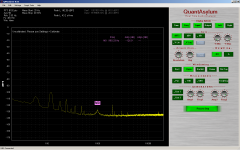
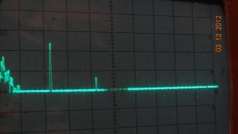
Injected harmonic level
Here both fundamental and second H level are set to -30dBV.
We can see the effect of the notch filter with out feedback.
The second is attenuated 12dB. Also the the 2kHz seems to be effecting the auto tune.
The fundamental is not being fully notched. The second oscillator is not great on distortion but surely is not generating sidebands.
Attachments
Okay so what's slowing it down then? 100 32k would appear to be real time.
I wasn't referring to the hardware. It's the OS that's being blamed.
Cheer,
The OS has nothing to do with it a 32K double precision FFT takes a few mSec just try it in Matlab or Mathcad or Octave (free). Even Cooledit 1998 will do 8K FFT's real time. You have to refine what you mean by real time, do you mean visible on screen latency or doing an entire FFT between audio samples (this is another matter).
Last edited:
The OS has nothing to do with it a 32K double precision FFT takes a few mSec just try it in Matlab or Mathcad or Octave (free). Even Cooledit 1998 will do 8K FFT's real time. You have to refine what you mean by real time, do you mean visible on screen latency or doing an entire FFT between audio samples (this is another matter).
Hi Scott,
I mean visually. The user experience.
I thought that was what Demiam was asking about.
Cheers,
Hi Scott,
I mean visually. The user experience.
I thought that was what Demiam was asking about.
Cheers,
OK that has to do with your GUI API, they are all over the place some have horrible overhead just so they are easy to program. The actual behind the scenes computation is lost in the round off.
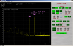
The milk is getting creamy 5dB at a time
I replaced U1 on the oscillator board with an LT1468, removed C45 and C48.
Not wanting to remove any more components or cut a trace I clipped pin 8 off the IC.
Pin 8 is not used but has rail voltage on it. I wish I could use at 1468 in the buffer stage but they don't do well with a 600 ohm load.
The feedback in the notch amp should stay as it is. As it is it's down 1dB at 2n H.
Cheers,
David
Attachments
What's been done so far
Here's the summery of what been done so far.
Oscillator:
Replaced A1U1 with LT1468 compensated version.
Clipped pin 8 off the 1468. It has power on it.
Removed A1C45 and A1C48.
Replaced A1U2 quad op amp with low noise Jfet type.
Changed A1R50 to 2,49K and paralleled a 20K trim. This is the 2nd H trim at 1KHz.
Optional is to replace A1C47 with 640pF to 1000 pF. This need to be experimented with.
It trims the distortion balance with 1KHz and 10KHz - 20KHz.
Clean and calibrate oscillator.
Analyzer:
Replaced A3U3 and A3U4 with OPA1641.
Removed A3C27 ans A3C26.
Replaced A4U1 with LT1468 uncomp.
Changed A4R1 to 200 ohm. Increases signal gain to 1000 for balanced multipliers.
Added 10pF feedback capacitor to A4U1 (1468)
Changed A4C47 to 1uF tan. Speeds up error signal to amplitude control of notch filter.
Connect FFT to TP3. Set input for 1KHz at 1Vrms on TP4. Calibrate notch level and phase roughly. Put FFT on A4 TP1. Set input balance trim for least amount of hash and harmonics. Repeat notch calibration.
Connect TP3 to AM input connector with mini coax. Find the best grounding point for AM (now output) which has least amount of hash and distortion.
I suggest isolating the ground of the BNC connector with extruded nylon washers. Then you get to choose.
There is still more to come. Lots more to do.
Cheers,
THD of parts -
Your on a roll.
I noticed there are electrolytic caps and trimmer controls that are not part of any feedback... for example the trim controls dropped thd by 6 db when replaced by better parts. Now, I see a pair of tantalum caps back to back as coupling caps. Well, that configuration reduces the cap distortion BUT we are after thd levels below what tant caps back to back provide.... I replaced the two tantalum back to backs (A3 C206,207) with a small 50v film cap and the third harmonic dropped another 6dB. No opamps have been changed, yet... waiting for adapters for the IC's to be mounted.
The THD (source plus analyzer) is now already 25 db below the -80db Full Scale, so we need a meter switch for X10 or -100dB F.S. range. When the opamps are changed, this will be more feasable (with the lower noise and distortion). Just need to trim the 2H down to much lower level. -Thx RNMarsh
Attachments
Last edited:
OK that has to do with your GUI API, they are all over the place some have horrible overhead just so they are easy to program. The actual behind the scenes computation is lost in the round off.
My ancient Wavetek plugin for a Tek 7K frame uses something like an intel 8008 processor. A zoomed view so i can see the harmonics or fundamental as I'm tuning with some averaging is slow.
The QA400 may be a good replacement. I emailed them and hope to hear back.
It looks like major progress on the venerable HP339. The work will help highlight the sensitivity and where to focus efforts in improving other analyzers.
Hi Demian,
It could be a week or so before you get an answer or maybe right away.
Was it the hardware, software or user experience you were asking about earlier?
Cheers,
Last edited:
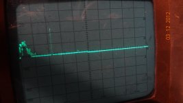
Oscillator.
I've got some weirdness going on with the oscillator.
The IC change may not have had the effect seen in the plots.
If the level range is switched range lower and the level brought up by the level pot the distortion drops 5dB on the 2nd H. It's the same level into the analyzer. The dial is broken off on this knob and I hadn't notice the range change. Now I have to figure out this odd behavior. The pot is between the oscillator and buffer amps.
- Home
- Design & Build
- Equipment & Tools
- Low-distortion Audio-range Oscillator