400K across 3.48K wouldnt change the amp gain at all. With full LED current, the LDR value will be lowest.
Hi Rick,
This was the LDR for the phase detector not the amplitude detector.
The impedance is much higher in the phase leg. If you look at the drivers for the LDRs you may notice they are biased differently. I will know better once I have an LDR out and test it proper.
Hello davada,
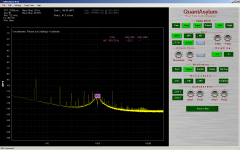
Could you say what FFT software do you use for your screenshot ?
Regards.
Frex
Hi Flex,
Yes QuantAsylum is fine with me saying who they are.
You can check out there web pages here.
QA Blog - QuantAsylum Home Page
There are some videos there you can watch on the QA400 software and hardware.
Cheers,
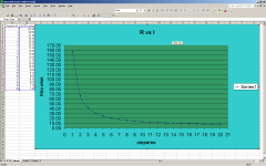
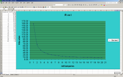
I hope that curve is in milliamperes. . .
Okay, Okay, I fix it.
The data columb says milliamperes.
I was wondering what that bad smell was.
Cheers,
Last edited:
so we shouldnt use it below 60K Ohms?? Adjust/scale it to be so??This better?
is Q of the notch high enough? More gain needed?
Can also measure THD of the LDR at different LED currents -- out of the box --- not in 339A circuit.
Thx... excellent detective work. -RNMarsh
If you check Nelson Pass's work he has already done that for the Silonex parts. Starts here:http://www.diyaudio.com/forums/analog-line-level/80194-lightspeed-attenuator-new-passive-preamp-133.html?postid=1520215#post1520215
All you will ever need to know. The Vactrol pdf (attached) has similar info as well. Also suggests that some DC will cause 2nd harmonic and pure AC 3rd harmonic. Very much a high voltage coefficient resistor.
All you will ever need to know. The Vactrol pdf (attached) has similar info as well. Also suggests that some DC will cause 2nd harmonic and pure AC 3rd harmonic. Very much a high voltage coefficient resistor.
Attachments
If you check Nelson Pass's work he has already done that for the Silonex parts. Starts here:http://www.diyaudio.com/forums/analog-line-level/80194-lightspeed-attenuator-new-passive-preamp-133.html?postid=1520215#post1520215
All you will ever need to know. The Vactrol pdf (attached) has similar info as well. Also suggests that some DC will cause 2nd harmonic and pure AC 3rd harmonic. Very much a high voltage coefficient resistor.
Hi Demian,
This all stands to reason then with my findings that the least amount of distortion, when operated as a series element, is when the LDR is near saturation or at least the LED current limit. The AC voltage across the LDR is at minimum.
Can some numbers be put to the DC influence? Are we talking uV, mV etc. I know you've made reference but I am lazy on the weekends.
Cheers,
Also suggests that some DC will cause 2nd harmonic and pure AC 3rd harmonic.
Those parts I've measured showed significant 2nd harmonic.
Can some numbers be put to the DC influence? Are we talking uV, mV etc.
Same order as the AC across the element.
Samuel
Those parts I've measured showed significant 2nd harmonic.
Same order as the AC across the element.
Samuel
Hi Samuel,
Did you log some data and perhaps stick it on your web pages?
Cheers,
Well, from the thd on the LDR, the lowest is at the spec for the 339A. That leaves -- the ser/par arrangment and a distortion cancelling method to remove thd of the LDR. Is there a simple circuit to linearize the LDR... harmonic cancelling... maybe with a second LDR mixed with control LDR? Or even a multi-turn pot in place of the LDR to get thd lower than LDR can do.-- worse case. -RNM
Well, from the thd on the LDR, the lowest is at the spec for the 339A. That leaves -- the ser/par arrangment and a distortion cancelling method to remove thd of the LDR. Is there a simple circuit to linearize the LDR... harmonic cancelling... maybe with a second LDR mixed with control LDR? Or even a multi-turn pot in place of the LDR to get thd lower than LDR can do.-- worse case. -RNM
That's assuming the thd is mostly coming from the LDRs in the 339a. I wasn't able to isolate this enough to know. I don't have the right value trims to do a manual tuning of the 339a notch. Otherwise I would have posted the results. I did the E2 LDR but not the E1.
It's not a bad assumption because I just can't see any other source for the distortion at these levels.
what if... adding DC offset to the opamp to bias out the 2nd from the LDR or just DC to the LDR...... cap couple the circuit output afterwards. ?? A DC trim pot/control.
I think what Samuel was saying is the DC is in the same proportions to the AC for it's effect on distortion. The offset from an op amp may be in the mV or even uV so I don't think this would have a significant impact on the 2nd H or 3rd H.
339a mod
Here is the latest.
I have averaging in the SW now so we can see more clearly.
I soldered a 50K trim pot across R48, the resistor to the non inverting input of the notch amp. The trim was adjusted so the total R is about 10K from the stock 15k. This forces the E2 LDR to operate at a lower resistance by increasing the gain of the notch amp. The auto tune has to compensate for the gain change. I also lowered the input voltage to the notch filter from 10Vrms to 1Vrms.
The effect of increasing the notch amp gain is a lower 3rd H and the 2nd H is about the same considering the scale change.
This is a what you see is what you get view.
The auto cal is temporarily non functional. The FS is at -0.5dB of dBV
Attachments
Last edited:
I am suggesting put external DC bias onto LDR to increase dc offset to the same as ac level or what ever level is needed to cancel 2nd. Thx-RNMI think what Samuel was saying is the DC is in the same proportions to the AC for it's effect on distortion. The offset from an op amp may be in the mV or even uV so I don't think this would have a significant impact on the 2nd H or 3rd H.
The manual trim above is useful to me. -130 for 3rd is very good. -110 for 2nd -- only need find a few more db's there to get to the source oscillator level.
Last edited:
I am suggesting put external DC bias onto LDR to increase dc offset to the same as ac level or what ever level is needed to cancel 2nd. Thx-RNM
The manual trim above is useful to me. -130 for 3rd is very good. -110 for 2nd -- only need find a few more db's there to get to the source oscillator level.
Okay I see where you're going with that.
One thing that will help is to attenuate the +10 dB HP normalizes to to 0dB at the input of the notch filter. The analyzer scale will be wrong but everything else will operate normally.
I guess everything else being the level mode.
I put a 50k ohm trim in series with the E1 LDR but didn't observe a drop in second H.
I'm wondering if the 339a oscillator is running a bit high in 2H right now.
The level setting pot is bad and might be getting in the way.
I could use one of Victor's oscillators right about now.
I'm wondering if the 339a oscillator is running a bit high in 2H right now.
The level setting pot is bad and might be getting in the way.
I could use one of Victor's oscillators right about now.
- Home
- Design & Build
- Equipment & Tools
- Low-distortion Audio-range Oscillator