Wow - recognized it! Seen a few demo videos a couple of days ago, and discovered myself wondering about release date. It looks great (particularly the H/W), and seems very promising indeed (although I'd add a few more FFT windows...) - need another beta tester?
L.
Hi coluke,
Just send a request to support@ tell them about yourself and what you do.
They want to clear up a few software problems before taking on more beta testers. But it's always good to get your name in.
Osc thd -
Another obvious place to look is the oscillator and the osc's buffer IC themselves. These IC were probably sota at the time but now we have much lower thd opamps that could be used in their place. The oscillator op-amp is running pretty hard at 20 volts p-p output. And, the buffer takes that and has to drive 600 ohm loads? That asking a lot of opamps of the era. I think we can drop the thd with those changes. Might also change the osc output to 10 v p-p and change the Buffer to a X2 gain stage. Even with stock opamp it would help. But that is harder with the agc and all there, too. So just changing to lower thd opamp on osc and its buffer; A1U1 and A1U3. - Thx RNMarsh [btw - who is your source for the opamps?)
It seems unlikely that those signals could be causing the distortion in the output. But their presence at all suggests the distortion is hiding under some rock nearby.
I would next try making the integrating caps on the level detectors larger and see if the harmonics increase or decrease. Those are the obvious nonlinear stage and driving them harder will show if they are coupling into the rest of the circuit.
The other candidate would be the LDR's themselves. Reading this thread DIYHiFi.org • View topic - LDR as a volume control suggests the LDR's in the 339 would be in the 2% THD generation. The Silonex parts would be substantially better. Looking at Nelson Pass's measurements you should keep the voltage across the LDR's below .2V or less. If they are the cause then a 20 dB improvement would be immediately visible. Perhaps you can look differentially across the LDR's in the 339?
Another obvious place to look is the oscillator and the osc's buffer IC themselves. These IC were probably sota at the time but now we have much lower thd opamps that could be used in their place. The oscillator op-amp is running pretty hard at 20 volts p-p output. And, the buffer takes that and has to drive 600 ohm loads? That asking a lot of opamps of the era. I think we can drop the thd with those changes. Might also change the osc output to 10 v p-p and change the Buffer to a X2 gain stage. Even with stock opamp it would help. But that is harder with the agc and all there, too. So just changing to lower thd opamp on osc and its buffer; A1U1 and A1U3. - Thx RNMarsh [btw - who is your source for the opamps?)
Last edited:
Another obvious place to look is the oscillator and the osc's buffer IC themselves. These IC were probably sota at the time but now we have much lower thd opamps that could be used in their place. The oscillator op-amp is running pretty hard at 20 volts p-p output. And, the buffer takes that and has to drive 600 ohm loads? That asking a lot of opamps of the era. I think we can drop the thd with those changes. Might also change the osc output to 10 v p-p and change the Buffer to a X2 gain stage. Even with stock opamp it would help. But that is harder with the agc and all there, too. So just changing to lower thd opamp on osc and its buffer; A1U1 and A1U3. - Thx RNMarsh [btw - who is your source for the opamps?)
Hi Rick,
The distortion we see from the 339A analyzer is about 20dB higher than the oscillator itself.
Yes the oscillator can be improved a bit but not that much more.
See Dick Moore's web page for details of tweaking the the 339A oscillator and you'll see what I mean.
Cheers,
Last edited:
More on the 339A
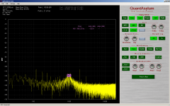
Further investigation of the 339A's elevated distortion from the analyzer revealed these results.
First I bypassed the E2 LDR with a trim pot. The distortion 2nd and 3rd H dropped about 5dB but I could only get the notch to -80dB with a pot. No surprise there. I re-soldered the LDR back in.
Demian suggested increasing the feedback cap of the integrator on the output of the amplitude error detector balanced modulator. I increased the cap from 47uF to 1000uF. This had no effect on the distortion. The notch would not settle to less than -95dB and took over 1 minute to do this. So I changed the cap to 10uF with no change in distortion level.
It stands to reason that the distortion is not produced by the phase detector or amplitude detector but by the LDR's.
Cheers,
Attachments
Last edited:
This is as far as I'm going with he 339A Analyzer.
In conclusion the remarkable notch depth is only obtainable with a lot of calibration effort.
It does not hold very well changing with level and frequency. I don't see an easy way of dealing with the elevated analyzer distortion and I don't think it's worth the money or time to try. I agree with the assessment of boat anchor as far as the analyzer is concerned.
The oscillator is very good and worth the improvement. The 339A works very well as a level meter and if you have the 001 option it can go right down to 10uV or better.
Cheers,
David.
Further investigation of the 339A's elevated distortion from the analyzer revealed these results.
First I bypassed the E2 LDR with a trim pot. The distortion 2nd and 3rd H dropped about 5dB but I could only get the notch to -80dB with a pot. No surprise there. I re-soldered the LDR back in.
It stands to reason that the distortion is not produced by the phase detector or amplitude detector but by the LDR's.
Cheers,
But you said the LDR only affected the thd by 5dB
 Which LDR?
 -RNM
Last edited:
But you said the LDR only affected the thd by 5dB
-RNM
E2 is the LDR for the amplitude control of the notch filter.
E1 is for the phase detector.
My aim was to identify the main source of the distortion and I am convinced it is the LDRs.
I think with both LDRs bypassed there would be reasonable drop in distortion but there is still the notch amp and feedback amp which contribute as well. Add in the input amp and buffer.
The Twin T is a better option since it is a passive notch filter. I would rather focus on an auto tune circuit for that than to modify the 339A.
Cheers,
David.
It looks like you did find the real distortion limiter. It would be interesting to know the voltage across the LDR in operation.
I agree that you may have hit a wall in the box. Its architectural. Unfortunately, even if you had the correct Silonex LDR's the distortion still may be limited unless its possible to get the voltage across the LDR's small. However my experience with the ST1700 suggests that the LDR's do age and may need replacement do to age.
If the opamps are LM318's and 5534's etc. they aren't a major limiter. They are in the KH4400 and it can get to less than -120 dB harmonics.
Modding it to use JFETs seems difficult, analog multipliers harder still and the lowest distortion option, servo pots, impractical in the extreme.
If the LDR is the primary distortion source, you can reduce its contribution by replacing it with a series-parallel combination of four LDRs. The combo has the same control law, but much lower distortion because each resistor element sees just half the AC voltage.
Samuel
Well since it is the LDR... where do I get some to use in a ser/par fashion? Who makes them? make and model to buy??
Thx - Richard
Well I was tired when I wrote the above. Maybe I will pursue it more later.
I forgot to re-solder the cap canceler back in and this will effect stability.
Any notch filter will be more stable if it is slightly off tuned from deepest notch but this just brings us back to where we started.
I'm wondering if we really need all the range HP put into the auto tune circuits. Maybe placing a fixed resistor across the LDRs would work and reduce the V across the LDR.
It's difficult to measure the V across the LDR because placing the probe across upsets the auto tune and circuit impedance. I can try using the TEK 7a22 diff amp PI and retuning for the
difference. This may put us in the ball park.
Cheers,
David.
Well since it is the LDR... where do I get some to use in a ser/par fashion? Who makes them? make and model to buy??
Thx - Richard
Silonex Silonex Inc.: Products: Audiohm Optocouplers Allied seems to be the US source. You will need to reverse engineer the parts in the box to match to Silonex part numbers. Please share when you figure it out. The Silonex parts should be much lower distortion than the original.
Unfortunately that number doesn't cross to a Vactrol part number. I found a good PDF on the parts from Vactrol here: VTL5C3/2 Datasheet pdf - Photoconductive Cells and Analog Optoisolators (Vactrols) - PerkinElmer Optoelectronics I don't know who if anyone still owns Vactrol. . . We need at least a dark resistance to figure out what parts are in it. Their charts also show the distortion descending to very low with less than .2 V RMS across the LDR. They also talk about aging.
Reducing the range of the autotune becomes an issue if the manual tune capability is limited. How much resolution dores the switching bring to the nulling? In the ST1700 I believe they left off the last digit or two to save money since it could tune that far.
Reducing the range of the autotune becomes an issue if the manual tune capability is limited. How much resolution dores the switching bring to the nulling? In the ST1700 I believe they left off the last digit or two to save money since it could tune that far.
I saw those pdf also. The web site should have a phone number somewhere to ask what the equiv p/n is now. Or a cross-reference. A clue to the (LD)R value is the fact that the LDR is across a resistor in the op-amp feedback.... (output to neg input) the value limits the range the LDR is effecting the opamp. That value is - 3.48K.
Unfortunately that number doesn't cross to a Vactrol part number. I found a good PDF on the parts from Vactrol here: VTL5C3/2 Datasheet pdf - Photoconductive Cells and Analog Optoisolators (Vactrols) - PerkinElmer Optoelectronics I don't know who if anyone still owns Vactrol. . . We need at least a dark resistance to figure out what parts are in it. Their charts also show the distortion descending to very low with less than .2 V RMS across the LDR. They also talk about aging.
Reducing the range of the autotune becomes an issue if the manual tune capability is limited. How much resolution dores the switching bring to the nulling? In the ST1700 I believe they left off the last digit or two to save money since it could tune that far.
The PerkinElmer LDRs are way up in distortion unless they are operated in the low 10%.
They do better if LP filtered. That is in series with a shunt cap to ground. But that was measured on the 339a. I have yet to re-measure using a spectrum analyzer and I might find it was mostly noise.
I will have the E1 and E2 LDR data ready tonight. They share the same part number.
Cheers,
David.
I saw those pdf also. The web site should have a phone number somewhere to ask what the equiv p/n is now. Or a cross-reference. A clue to the (LD)R value is the fact that the LDR is across a resistor in the op-amp feedback.... (output to neg input) the value limits the range the LDR is effecting the opamp. That value is - 3.48K.
The 3.48k resistor is worked in a very narrow R range. So the LDR can be 400K and up.
I measured 402K with the max drive current into the LDR for the phase detector circuit on the 339a when the LDRs were lifted. The drive circuit was saturated under this condition.
Cheers,
- Home
- Design & Build
- Equipment & Tools
- Low-distortion Audio-range Oscillator