Merry Christmas
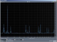
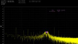
Last night I took my C7 red lamp and grabbed 6 - .033uF film caps out of the same bag and 6 - 1260 Ohm resistors sequentially off the same strip and wired up Mr. Brisbois' oscillator and a mating notch. Using the AD797 here's a quick picture of the results. Out of the box the notch was -46dB and the amplitude was 5.3V rms (~15.7V p-p) at ~4k Hz. There are my annoying Aglient vibration sidebands (without care they contaminate all my vibration sensitive measurements). THD pretty good though, -135dB seconds, -126dB thirds, after fourths in the noise.
On a fanless brick supply the vibration should go way down. This could be a great op-amp rolling opportunity.") And BTW this is just a chip and wire on ratshack board.
And BTW this is just a chip and wire on ratshack board.
EDIT - Yup forgot the notch correction, still below -120dB I think, jeesh.
Last night I took my C7 red lamp and grabbed 6 - .033uF film caps out of the same bag and 6 - 1260 Ohm resistors sequentially off the same strip and wired up Mr. Brisbois' oscillator and a mating notch. Using the AD797 here's a quick picture of the results. Out of the box the notch was -46dB and the amplitude was 5.3V rms (~15.7V p-p) at ~4k Hz. There are my annoying Aglient vibration sidebands (without care they contaminate all my vibration sensitive measurements). THD pretty good though, -135dB seconds, -126dB thirds, after fourths in the noise.
On a fanless brick supply the vibration should go way down. This could be a great op-amp rolling opportunity.
And BTW this is just a chip and wire on ratshack board.EDIT - Yup forgot the notch correction, still below -120dB I think, jeesh.
Attachments
Last edited:
wired up Mr. Brisbois' oscillator and a mating notch.
Glen has some comments on the oscillator on EDN -- most shocking was that he tried out the Carthusians before becoming an engineer -- talk about "sheesh". The Carthusians won't let Jesuits "retreat" at their monasteries.
Glen Brisebois's Profile | EDN
Glen has some comments on the oscillator on EDN -- most shocking was that he tried out the Carthusians before becoming an engineer -- talk about "sheesh". The Carthusians won't let Jesuits "retreat" at their monasteries.
Glen Brisebois's Profile | EDN
Done the Jesuit retreat thing. Trappists too I see, they make beers and a "Stinking Bishop" cheese to go with it in Belgium.
I see he comments somewhere else that he used C_opt (added underscore) so Egyptian Christians won't accidentally find his article.
339a mods
I really wasn't planning on doing any mods to the 339a at this time.
But I just can't resist.
So this is what I did.
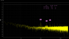
I increased the gain from 200 to 1000 of the amplifier that supplies the phase and level detectors which is fed from the notch filter output. Since this narrows the BW, I replace the 318 with an LT1468 to get a 100KHz BW and added a 10pF cap in the feedback of the 1468. This only bought me 5 - 7dB on the notch so I changed the notch and notch feedback op amps from HA2-2526 to OPA1641.
A3U3 and A3U4 are OPA1641. A4U1 is a LT1468 with 10pF comp. and A4R1 is 200 ohms.
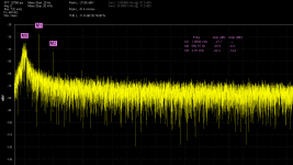
This is with a +10dB scale so what you see is 10dB lower, bouncing between -135dB and -137dB
The disto is about the same. I have to work on that.
1KHz at 1Vrms input, all filters in. The meter reads 0.0014%
The 339A adds +10dB before the notch filter input.
I really wasn't planning on doing any mods to the 339a at this time.
But I just can't resist.
So this is what I did.
I increased the gain from 200 to 1000 of the amplifier that supplies the phase and level detectors which is fed from the notch filter output. Since this narrows the BW, I replace the 318 with an LT1468 to get a 100KHz BW and added a 10pF cap in the feedback of the 1468. This only bought me 5 - 7dB on the notch so I changed the notch and notch feedback op amps from HA2-2526 to OPA1641.
A3U3 and A3U4 are OPA1641. A4U1 is a LT1468 with 10pF comp. and A4R1 is 200 ohms.
This is with a +10dB scale so what you see is 10dB lower, bouncing between -135dB and -137dB
The disto is about the same. I have to work on that.
1KHz at 1Vrms input, all filters in. The meter reads 0.0014%
The 339A adds +10dB before the notch filter input.
Attachments
Last edited:
I really wasn't planning on doing any mods to the 339a at this time.
But I just can't resist.
So this is what I did.
I increased the gain from 200 to 1000 of the amplifier that supplies the phase and level detectors which is fed from the notch filter output. Since this narrows the BW, I replace the 318 with an LT1468 to get a 100KHz BW and added a 10pF cap in the feedback of the 1468. This only bought me 5 - 7dB on the notch so I changed the notch and notch feedback op amps from HA2-2526 to OPA1641.
A3U3 and A3U4 are OPA1641. A4U1 is a LT1468 with 10pF comp. and A4R1 is 200 ohms.
This is with a +10dB scale so what you see is 10dB lower, bouncing between -135dB and -137dB
The disto is about the same. I have to work on that.
1KHz at 1Vrms input, all filters in. The meter reads 0.0014%
The 339A adds +10dB before the notch filter input.
I am really glad you did these changes and tested the results... I am REALLy getting excited, now. I have ordered the IC's you used. cant wait. Thx-RNMarsh
I am really glad you did thiese changes... I am REALLy getting excited, now. I have ordered the IC's you used. cant wait. Thx-RNMarsh
Hi Rick,
This is at the calibration frequency and level. There is no guarantee to get this at other settings. There may be variation from one 339a unit to another. There is no guarantee you will get the same results.
You will have to do a notch filter calibration after the mod.
Better yet do a full calibration.
I do think this will provide some improvement.
Cheers,
Last edited:
Isolated notch filter
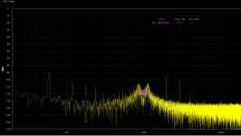
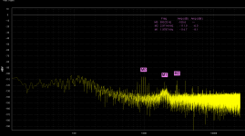
This is the 339a notch filter completely isolated.
The input of the notch filter is connected directly to the output of the oscillator and measurement is right off the output of the notch filter.
The capacitance canceler is disabled by removing the coupling resistor.
I removed the shunt capacitors on the notch and notch feedback op amps because they are not needed by the opa1641 and I felt the load might raise distortion levels. Didn't make any difference. Removing the capacitance canceler didn't make any difference either so I'll put it back in because it does affect the null.
As you can see there is no change in distortion at all. So it is the notch filter raising the disto.
The question is which part?
Cheers,
Attachments
Could it be the same phenomena that affects the AGC in the oscillator? Ripple etc. on the amplitude/phase controls?
I'll have a look and post some data.
Cheers,
Hello davada,
Could you say what FFT software do you use for your screenshot ?
Regards.
Frex
Hi Flex,
I don't know that I can at this time because I'm involved with the beta test program for the hardware and software. That's why I obscured the name. Its not ready for release but I will ask if I can share what it is.
It is very near an EMU0204 and ARTA in performance.
Cheers,
David.
Ok, thank you!
I follow from many years all of available FFT softwares, and i didn't recognized the screenshot .. I will be interesting to know if it's a new software if it's a commercial product (or not?).
Regards.
Frex
It is geared to be a commercial product but priced in the same range as an EMU0204 and a licensed copy of ARTA. I think it will be tailored for audio and production line testing.
Cheers,
David.
Ok, thank you!
I follow from many years all of available FFT softwares, and i didn't recognized the screenshot .. I will be interesting to know if it's a new software if it's a commercial product (or not?).
Regards.
Frex
This is the control panel.
Attachments
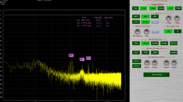
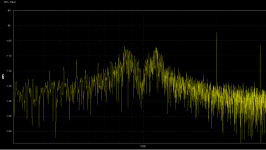
This is TP1 and TP2 error signals off the phase and level detectors.
This is what is sent to the LDR's
It seems unlikely that those signals could be causing the distortion in the output. But their presence at all suggests the distortion is hiding under some rock nearby. It could be as simple as the harmonics from the level detector getting back in via a shared ground. Not an issue if you stop at -80 dB. Big issue if you are going for below -100 dB.
I would next try making the integrating caps on the level detectors larger and see if the harmonics increase or decrease. Those are the obvious nonlinear stage and driving them harder will show if they are coupling into the rest of the circuit.
The other candidate would be the LDR's themselves. Reading this thread DIYHiFi.org • View topic - LDR as a volume control suggests the LDR's in the 339 would be in the 2% THD generation. The Silonex parts would be substantially better. Looking at Nelson Pass's measurements you should keep the voltage across the LDR's below .2V or less. If they are the cause then a 20 dB improvement would be immediately visible. Perhaps you can look differentially across the LDR's in the 339?
This is the control panel.
Wow - recognized it! Seen a few demo videos a couple of days ago, and discovered myself wondering about release date. It looks great (particularly the H/W), and seems very promising indeed (although I'd add a few more FFT windows...) - need another beta tester?
L.
- Home
- Design & Build
- Equipment & Tools
- Low-distortion Audio-range Oscillator