Time of year to find plenty of C7 bulbs.
Referring to this article: Injection-lock a Wien-bridge oscillator
EDN Glen Brisebois - October 31, 2012
Injection-lock a Wien-bridge oscillator | EDN
I think you are saying that the auto set level is done with an LDR pair at the input to the notch filter that maintains the level there at 3.16V RMS. The LDR's will be a limiter for the distortion. You could upgrade them to the Silonex equivalent which are supposed to be better or use several in a series/parallel network to reduce the voltage drop across them which will reduce the distortion. The distortion is voltage (or maybe current, I'm not sure) dependent so a smaller signal is lower distortion.
A constant level in the notch is pretty important for the auto-notch circuits to work. If you tap before the level meter attenuator for an external FFT you will have a pretty predictable level/known distortion level on the monitor out. If your FFT has low enough noise and the notch circuit is low noise then you should have all you need.
The FET opamp probably has better common mode rejection than the original which will reduce the internal distortion.
Hi Demian,
This first screen shot is with the 339a in level mode and the second is the same input level in distortion mode all from the monitor output.
Attachments
I think I might use that AM detector input as the notch output port. I will never use the AM det. so i can just unsolder that wire and replace it with the notch output and have a nice convenient front panel port.
Good idea Rick.
We have to test the theory first. I haven't tried this.
If we use the monitor output switched to the notch output then the Am input can be used to monitor the RMS detector output or what ever your preference. This will give an exact rms input level to the notch filter and scaling is simple from here.
If padding is going to be used it is best to place it right at the output of the notch filter amp. This offers isolation of the op amp to the external.
The wide band amplifiers used in the 339a are prone to RF parasitic oscillation so we have to be careful about what we do.
I will touch on this in another post.
Last edited:
I now follow. Its similar to the auto set level in the ST1700 series. The input is manually ranged (detail I had forgotton) and the output has a small AGC range to track the input across a 5:1 range or so. In the St17XX it can be defeated with a manual knob. You are indicating that the 339 doesn't have a manual adjustment? Still an AGC across that range should have very little distortion. The second harmonic you show is typical for LDR's. (The Lightspeed attenuator guys don't seem to see this?)
Looking at the circuit finally I see how it works. I think the easy change would be to get two or four matched Silonex LDR's and convert. Also returning the ground on the Distortion analyzer LDR to a more optimum location should reduce the crosstalk and distortion coming in via that common connection. Remember the specs for the HP339 were -80 dB, not -100 dB+. Good engineering generally stops pursuing a infinite goal when you meet the specs with reliability and good yield. Improving in this case may just be attention to details like this.
Does anyone have specs on the "photomodule"? or measurements of resistance vs current? What is needed is a cold, off DCR. Preferably after it has been completely off for 4-5 hours. Then 100 uA, 1mA and 10 mA will give a good clue as to its R vs I curve and matches can be found. That stage should have less than .1 % distortion. Actually, since the fundamental has been removed its not clear where the distortion is getting, in except from the notch filter itself. Noise will be a function of resistor values and the noise from the source. Look for really low noise FET opamps for the notch?
Checking the system calibration with a second oscillator mixed in at -40 or -60 dB will help with reality verification.
I now follow. Its similar to the auto set level in the ST1700 series. The input is manually ranged (detail I had forgotton) and the output has a small AGC range to track the input across a 5:1 range or so. In the St17XX it can be defeated with a manual knob. You are indicating that the 339 doesn't have a manual adjustment? Still an AGC across that range should have very little distortion. The second harmonic you show is typical for LDR's. (The Lightspeed attenuator guys don't seem to see this?)
Looking at the circuit finally I see how it works. I think the easy change would be to get two or four matched Silonex LDR's and convert. Also returning the ground on the Distortion analyzer LDR to a more optimum location should reduce the crosstalk and distortion coming in via that common connection. Remember the specs for the HP339 were -80 dB, not -100 dB+. Good engineering generally stops pursuing a infinite goal when you meet the specs with reliability and good yield. Improving in this case may just be attention to details like this.
Does anyone have specs on the "photomodule"? or measurements of resistance vs current? What is needed is a cold, off DCR. Preferably after it has been completely off for 4-5 hours. Then 100 uA, 1mA and 10 mA will give a good clue as to its R vs I curve and matches can be found. That stage should have less than .1 % distortion. Actually, since the fundamental has been removed its not clear where the distortion is getting, in except from the notch filter itself. Noise will be a function of resistor values and the noise from the source. Look for really low noise FET opamps for the notch?
Checking the system calibration with a second oscillator mixed in at -40 or -60 dB will help with reality verification.
Hi Demian,
I don't think the distortion from the auto set is very significant at the tiny levels coming from the notch filter. However this is an lm318 following the notch filter. Not the best by today's standards. What your suggesting will help the 339a analyzer, but I still think shortening the signal change is the answer. There is still the question of the LDR in the notch filter and I think we can still do better with a different op amp here as well.
It's not my goal to hot rod the 339a more than I have because I don't think this form of analysis is the best. Notch then FFT is what works for me. We can make good use of what we have with the front end of the 339a which is what's missing from our sound card FFT arrangement. So any improvements are focused here.
Additionally, the phase detector can use some attention as well. At bit more gain at the input might bring the notch down more and getting the noise down some may help because the at this point the notch is near the noise floor and there's nothing left to work with.
Also the band width of the input op amp to the phase comparator is a bit narrow which effects the higher frequency null. Actually with sound card and FFT the null doesn't need to be that deep but noise is an issue.
But all this needs to looked at in more detail.
Also tieing another resistor to the gate of Q3 on the auto set level board and to an appropriate supply will allow the AGC to be shut off and the stage becomes unity gain. Minimal mod fix.
These all great suggestions which don't require hacking the 339a at all.
Minimal is good.
Also tieing another resistor to the gate of Q3 on the auto set level board and to an appropriate supply will allow the AGC to be shut off and the stage becomes unity gain. Minimal mod fix.
There is a test point sitting right beside U10 + input so we don't even have to do any soldering here
and test point 1 is on the output of the RMS detector.
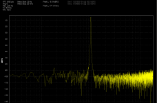
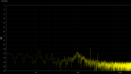
Test point 8 of 339a
With all else the same this is a screen shot of test point 8.
The output of the notch filter. As you can see the noise floor is much lower but
still has the x3 scaling from the input amplifier. With this scaled down 3:1 we have a nice spectrum of the input.
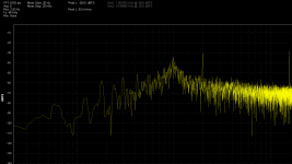
The second shot is with the input attenuator stepped up to the next 3Vrms range.
The harmonics change proportionally but the notch didn't change as much.
Definitely needs to be attenuated on the output side of the notch filter.
It looks like it needs to be scaled down about 45dB to get the true value which seems kind of odd. I'll need to see what the actual level is going in to the notch.
This is the residual noise floor of the input, buffer and notch filter. The notch won't go any lower than this. This is pretty much the bottom line for this analyzer as it is.
Overall this is much better.
With all else the same this is a screen shot of test point 8.
The output of the notch filter. As you can see the noise floor is much lower but
still has the x3 scaling from the input amplifier. With this scaled down 3:1 we have a nice spectrum of the input.
The second shot is with the input attenuator stepped up to the next 3Vrms range.
The harmonics change proportionally but the notch didn't change as much.
Definitely needs to be attenuated on the output side of the notch filter.
It looks like it needs to be scaled down about 45dB to get the true value which seems kind of odd. I'll need to see what the actual level is going in to the notch.
This is the residual noise floor of the input, buffer and notch filter. The notch won't go any lower than this. This is pretty much the bottom line for this analyzer as it is.
Overall this is much better.
Attachments
Last edited:
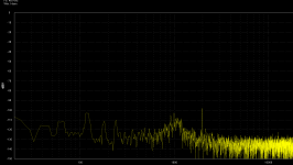
Wrong test point
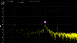
It seem I was measuring off the wrong test point TP8 and TP9.
These test point are post distortion amp levels.
Here is 1Vrms input and 3Vrms input straight off the notch filter output.
These level are at +10dBV scale.
The notch filter has added to the second and third harmonic level.
This is not bad but still not as good as Dick Moore's Twin T.
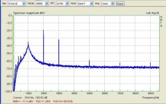
Attachments
Last edited:
It seem I was measuring off the wrong test point TP8 and TP9.
These test point are post distortion amp levels.
Here is 1Vrms input and 3Vrms input straight off the notch filter output.
These level are at +10dBV scale.
The notch filter has added to the second and third harmonic level.
This is not bad but still not as good as Dick Moore's Twin T.
Is this on a stock unit or modified in certain ways?
Referring to this article: Injection-lock a Wien-bridge oscillator
EDN Glen Brisebois - October 31, 2012
Injection-lock a Wien-bridge oscillator | EDN
Read the comments, Jim Williams was surprised by the results. I have a nice red bulb going right now the settling is much slower than the standard lamp which by theory indicates better distortion. AD797 and AD844 work fine but a NOS OPA627 never settles in amplitude, I will report tomorrow.
Is this on a stock unit or modified in certain ways?
Hi Rick,
The oscillator has the channel modulation trim pot and the parallel cap value increase.
The notch filter op amp was replaced with a jfet type of poor quality for this job.
But the notch depth under certain conditions is better or the same.
I think the OPA1641 is a better choice for the notch amp.
Otherwise it is a stock unit. I have the 001 option with mine but that shouldn't make any difference for this. It's just an extended range option.
The result is almost as good as Twin T.
The spectrum should look better with some averaging applied but like I said the unit have is in beta and I can't add averaging right now.
Last edited:
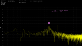
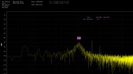
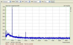
Two 339A monitor out spectra
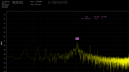
These are taken from the monitor output; this 339 has not been cal'd in some time -- more than a year. Even so, at last cal I used two oscillators to verify the accuracy of the output levels for distortion readings down to -90dB, and I have no reason to think they are in any way inaccurate.
The input is from the 339 osc. at 1kHz, at 1VRMS, with a high-Z load of the analyzer only (not into 600 ohms), which means that the monitor output's 0dBV level of 1VRMS full-scale is referenced to 1VRMS at the 339 analyzer input (in analyzer mode, the THD read about 0.0013% with all filters in, but the actual THD of the osc. is more than 20dB lower).
The first plot is the full-scale signal at 0dBV, even though I've raised the plot 10dB to show the floor -- note the 0.0dB RMS reading in red. The 400Hz HP filter is in, the two LP filters are out -- they are noisy and have distortion even though they do clean up the meter readings. Note the 2nd H at about -94dB, and the 3rd H at about -86dB (I'll go back and turn the 400Hz HP off, too, and see if that changes anything -- I've just always left that in).
The second plot is the monitor distortion output with the distortion range set to the max sensitivity of -80dB, so the plot's 0dBV level is actually -80dB. The notched fundamental is about -35dB = -115dB. The 2nd H is about -100dB, and the 3rd H is about -111dB. I don't know where the high Hs are coming from -- I really don't want to tear the 339 open just now, as I'm bring a Fluke 343A DC voltage standard back to life. Davada may figure it out for us....
Attachments
It would seem that the Level control generates 10% distortion, second harmonic only. That is way higher than the Silonex claims and more than I would have expected. You would have a pretty small signal at that node so I think some other factor could be contributing. How much ripple is on the LED drive (TP3)?
Unless something is very wrong X100 or 40 dB should be in the .01 % THD or less region even with a 741.
A diagnostic check would be to kill the LDR (Pull the FET to off, negative) and drop in a resistor, 50 Ohms or so, in parallel with the LDR to get X100 from the stage. Try returning the resistor to several possible "optimum" grounds to see which has the lowest harmonic contribution.
A diagnostic check would be to kill the LDR (Pull the FET to off, negative) and drop in a resistor, 50 Ohms or so, in parallel with the LDR to get X100 from the stage. Try returning the resistor to several possible "optimum" grounds to see which has the lowest harmonic contribution.
Unless something is very wrong X100 or 40 dB should be in the .01 % THD or less region even with a 741.
A diagnostic check would be to kill the LDR (Pull the FET to off, negative) and drop in a resistor, 50 Ohms or so, in parallel with the LDR to get X100 from the stage. Try returning the resistor to several possible "optimum" grounds to see which has the lowest harmonic contribution.
Hi Demian,
The x100 is a stage just before the meter amp and is down stream from the auto set level.
The auto set level never sees this much gain since the input range selector and nag indicators keep the level within the 3.162Vrms FS for the most part.
- Home
- Design & Build
- Equipment & Tools
- Low-distortion Audio-range Oscillator