R1 = R2 = 110k and R4 = 30k would propably be a very sensible change to my circuit, and enable well below -140 dB multiplier distortion contribution, with still excellent noise. If I find time I'll try this out.
Samuel
This certainly puts it down to component selection, and beats most everything. I think the FET's win on noise at the expense of a little distortion, though the seconds can be trimmed. Has anyone tried the JFET's specifically for VCR's
This certainly puts it down to component selection, and beats most everything. I think the FET's win on noise at the expense of a little distortion, though the seconds can be trimmed. Has anyone tried the JFET's specifically for VCR's
Hi Scott,
I sent a few of the original VCR jfets used in the HP339A to Dick Moore.
As I recall they did not win over the 2n4391/2/3 or is it the 2n4091/2/3 he compared them to.
Perhaps Dick can comment on this.
Hi,
I wish to show MMBF4391 JFET (as VCR) distortions measurement results. I used one of my 1kHz generators as signal source. Measured output from JFET was connected through buffer to Asus Xonar D2 soundcard (previously some improvements made in this soundcard). Schematic for measurement:

1) Test measurement with 68ohm resistor instead of JFET. Input voltage 7.6V p-p. App. 40mV p-p on resistor:

2) Same input voltage. Same 40mV p-p on JFET:
http://content8-foto.inbox.lv/albums/e/elterra/FETmeasurement/FET40mV.jpg
3) Input voltage 3.8V p-p. 20mV p-p on JFET:
http://content8-foto.inbox.lv/albums/e/elterra/FETmeasurement/FET20mV.jpg
Victor
I wish to show MMBF4391 JFET (as VCR) distortions measurement results. I used one of my 1kHz generators as signal source. Measured output from JFET was connected through buffer to Asus Xonar D2 soundcard (previously some improvements made in this soundcard). Schematic for measurement:
1) Test measurement with 68ohm resistor instead of JFET. Input voltage 7.6V p-p. App. 40mV p-p on resistor:
2) Same input voltage. Same 40mV p-p on JFET:
http://content8-foto.inbox.lv/albums/e/elterra/FETmeasurement/FET40mV.jpg
3) Input voltage 3.8V p-p. 20mV p-p on JFET:
http://content8-foto.inbox.lv/albums/e/elterra/FETmeasurement/FET20mV.jpg
Victor
At AES yesterday I badgered the SRS sales guy to show me the residual distortion measured with his SR1 audio analyzer. Its approx -115 to -118 for the first two harmonics. He said they use a digital generator and analog low pass filter to get the performance.
Its a valid but very complex way to get low distortion. Not easily done.
The instrument also has a really good jitter/phase noise analyzer function. I will try to visit them soon and get a good demo of it with my sources.
Its a valid but very complex way to get low distortion. Not easily done.
The instrument also has a really good jitter/phase noise analyzer function. I will try to visit them soon and get a good demo of it with my sources.
Those seem to be exceptional results. I am not sure I understand the measurement conditions. The reference voltage (1 KHz) is the 40mV or 20mV across the FET?
Yes. Measurement conditions are 40mV p-p or 20mV p-p across the FET.
Victor
Hi,
I wish to show MMBF4391 JFET (as VCR) distortions measurement results. I used one of my 1kHz generators as signal source. Measured output from JFET was connected through buffer to Asus Xonar D2 soundcard (previously some improvements made in this soundcard). Schematic for measurement:
Victor
The last one looks pretty good, I doubt there is a much better FET.
Hi Victor,
Thanks for doing this.
It's important to know what the dc gate voltage is.
If you have time could you repeat this at different Vg for comparison?
If I remember correctly from tests I did over a year ago on a Jfet type multiplier,
there is a sweet spot and a sour spot within the range of Vg used.
Thanks for doing this.
It's important to know what the dc gate voltage is.
If you have time could you repeat this at different Vg for comparison?
If I remember correctly from tests I did over a year ago on a Jfet type multiplier,
there is a sweet spot and a sour spot within the range of Vg used.
Hi Victor,
Thanks for doing this.
It's important to know what the dc gate voltage is.
If you have time could you repeat this at different Vg for comparison?
If I remember correctly from tests I did over a year ago on a Jfet type multiplier,
there is a sweet spot and a sour spot within the range of Vg used.
DC gate voltage in this case was app. -3.9V. This voltage may varies depending of individual transistor example. Transistor, which has bigger Vgs OFF, has better distortions performance in same conditions (equal Rds).
Victor
Those seem to be exceptional results.
You can get every sensible variable gain element to show essentially arbitrary low distortion by reducing the signal level across it--at the cost of higher noise. As Bob mentioned, we need a figure of merit for the multiplier which catches this tradeoff (I'm thinking about it).
Samuel
Wouldn't using two JFETs in a differential fashion be a way to reduce remaining nonlinearity of Rds vs Vds? I mean, one JFET as is on the input side of the summing junction and another matched one coming from the output, each with their series resistors. Then feeding the second one a copy of the control voltage (with additional DC bias) so that the Rds changes do work in "push-pull". Compressing/Expanding distortion vs signal would pretty much cancel out, only the difference of the Rds vs Vds nonlinearities would be effective. Also, for freqs above tuning the CV could be injected in opposite polarity (with an 1st order allpass phase shifter) so that high frequency CV ripple and noise would change both Rds' almost in phase, producing little effect on the total gain.
Just a few thoughts... well, another one : Would an expansion of the amplitude detector as shown in the EDN article to four quadrants (with 90deg phase shifters) produce any benefits? I could see faster settling as well as less and higher freq ripple of the detector output. I simmed this already and it's looking good and has not too much circuit overhead.
Just a few thoughts... well, another one : Would an expansion of the amplitude detector as shown in the EDN article to four quadrants (with 90deg phase shifters) produce any benefits? I could see faster settling as well as less and higher freq ripple of the detector output. I simmed this already and it's looking good and has not too much circuit overhead.
Last edited:
Properly built JFET VCR can be reduced to simplified schematic and it is absolutely symmetrical:Wouldn't using two JFETs in a differential fashion be a way to reduce remaining nonlinearity of Rds vs Vds?

In my opinion, differential fashion is not needed, cause this fashion reduce only nonsymmetry. In the other hand, when we use two or more JFET VCRs in series, AC gain drops in every JFET and this is a way for to reduce distortions. But, I do not know at this time, which way is better: more than one JFET in series, or simple signal amplification from one JFET. This situation must be analyzed from different courses: noise, easy to bulid, cost...
Victor
Properly built JFET VCR can be reduced to simplified schematic and it is absolutely symmetrical:
In my opinion, differential fashion is not needed, cause this fashion reduce only nonsymmetry. In the other hand, when we use two or more JFET VCRs in series, AC gain drops in every JFET and this is a way for to reduce distortions. But, I do not know at this time, which way is better: more than one JFET in series, or simple signal amplification from one JFET. This situation must be analyzed from different courses: noise, easy to bulid, cost...
Victor
I chose the 4091 JFET for my original oscillator based on high threshold and low Vds_on. This seems to keep the FOM high.
If one is using optimized drain feedback to the gate, this tends to kill the second harmonic distortion, leaving only 3rd, which would seem to be about what using two JFETs differentially would do.
BTW, I believe I originally saw the JFET AGC element with gate feedback on an HP oscillator. I don't remember the model or when it was designed, but I saw the schematic around 1970.
I used to devour schematics in the user manuals of HP test equipment at the time where I worked (BTL).
Cheers,
Bob
Figure with noise vs. Vc of post #797 fixed.
I've just quickly checked this with my current prototype oscillator, and the control voltage from 10 Hz to 100 kHz was below +-200 mV (multiplier scaling factor 0.05, multiplier decoupling 10x). So it looks like that, for sufficient leveling authority alone, a multiplier authority of 5m should be well sufficient for a carefully design SVF oscillator. The tradeoff is mostly with respect to settling time.
Would still be interested to see this data for the Cordell oscillator, if anyone has time!
Samuel
BTW, Bob, could you post a graph of multiplier control voltage vs. frequency for your oscillator? This would be interesting to determine the necessary multiplier authority.
I've just quickly checked this with my current prototype oscillator, and the control voltage from 10 Hz to 100 kHz was below +-200 mV (multiplier scaling factor 0.05, multiplier decoupling 10x). So it looks like that, for sufficient leveling authority alone, a multiplier authority of 5m should be well sufficient for a carefully design SVF oscillator. The tradeoff is mostly with respect to settling time.
Would still be interested to see this data for the Cordell oscillator, if anyone has time!
Samuel
Wouldn't using two JFETs in a differential fashion be a way to reduce remaining nonlinearity of Rds vs Vds? .
I've tried this and there was no improvement over the single FET. Paralleling FET's to have lower Rdon for the same Vp might help. If you read part two of my Linear Audio article you will find a hint on how to make Victor's idealized VCR exactly, floating and completely isolated from the control voltage. I will draw it up tonight.
SW -- Where are you getting all this free time... retired, yet? is every day, Saturday yet?
I took vacation for my niece's wedding and the storm intervened. So I have some peace to work on things that would not get done while I watch all 10 Jason movies.
Here's my idea. The photovoltaic MOSFET driver generates a small isolated current with up to 8V compliance. You just force this current into a large resistor to control the gate voltage of the VCR. The RC can be at a very low frequency rather easily. I envision a second control channel could be used to cancel the thirds, thinking out loud right now.
Attachments
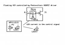
That floating VCR controlled by a Photovoltaic MOSFET driver is rather clever. The isolated control opens up some possibilties.
I think that it is similar in function to the Photo FET Optocouplers like the Fairchild H11F1M but lower distortion.
I am messing around with ideas to meet Samual Groner's reasonable and realistic design goal for a very good DIY oscillator. Progress is slow though because I am back at work unfortunately (bad for my sanity but good for the bank balance).
There are some other parameters to consider.
Output impedance. I prefer relatively low, < 100 ohms, it's always possible to add resistance externally.
Single ended or differential output, semi or true differential. I think that floating single ended is good enough for normal use.
DC or AC coupled. I prefer AC coupling.
- Home
- Design & Build
- Equipment & Tools
- Low-distortion Audio-range Oscillator