Hi,
looks like Samuel was right and the shown results were unreal in terms of absolute levels. The synced averaging and the AP graphing methods are to be taken with a grain of salt (and there are still some real and annoying bugs in the control software), especially for less experienced operators like me.
==> Forget the previous plot I posted in #730.
----:----
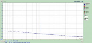
I measured again, now with traditional spectrum averaging (128x) and results are way more realistic now. The differences between the DUTs, though, remain fairly constant.
Two pcs. of Viktors' 1kHz Osc were tested, I see a slight increase of LF noise vs AP Genmon and the SG505 but the harmonic purity is outstanding and seems to be consistent.
I also looked at settling after a level change, at high level settings it settles quite fast while a the low end (at 300mVrms) it bounces up and down a little for some seconds.
looks like Samuel was right and the shown results were unreal in terms of absolute levels. The synced averaging and the AP graphing methods are to be taken with a grain of salt (and there are still some real and annoying bugs in the control software), especially for less experienced operators like me.
==> Forget the previous plot I posted in #730.
----:----
I measured again, now with traditional spectrum averaging (128x) and results are way more realistic now. The differences between the DUTs, though, remain fairly constant.
Two pcs. of Viktors' 1kHz Osc were tested, I see a slight increase of LF noise vs AP Genmon and the SG505 but the harmonic purity is outstanding and seems to be consistent.
I also looked at settling after a level change, at high level settings it settles quite fast while a the low end (at 300mVrms) it bounces up and down a little for some seconds.
Attachments
Thanks very much for revising the measurements--that looks valid now!
The exact performance of the SYS-2722 depends a bit on the age, as later units have certain improved subcircuits. The one I'm using has around -135 dB (analyzer) and probably -140 dB (generator--measured with passive notch filter) 2nd and 3rd harmonic residual at 1 kHz.
So in your plot the distortion for Victor's oscillator could well be from the analyzer.
Samuel
PS: Yes, the synced average mode is tricky. Hardly ever use it therfore.
PS: Yes, the synced average mode is tricky. Hardly ever use it therfore.
It seems that in the previous plot there was no actual signal to sync on both for Victor's and AP's internal generator (or signal level was by far too low to get a stable sync) - I must admit the first plot was almost frightening

L.
In my experience long averaging (5,000,000 point 10 averages) even crystal controlled sources can drift enough to degrade the measurements. You can see the harmonics moving from bin to bin with successive measurements.
Is the AP oscillator stabilized (disciplined)? It shows less close in phase noise than Victors.
Is the AP oscillator stabilized (disciplined)? It shows less close in phase noise than Victors.
Our AP is about two years old, is that late enough?The exact performance of the SYS-2722 depends a bit on the age, as later units have certain improved subcircuits. The one I'm using has around -135 dB (analyzer) and probably -140 dB (generator--measured with passive notch filter) 2nd and 3rd harmonic residual at 1 kHz.
So in your plot the distortion for Victor's oscillator could well be from the analyzer.
It shows less close in phase noise than Victors.
Yeah - I was wondering about Victor's phase noise and THD+N. A full spectrum comparison betweem AP's and Victor's would be interesting.
L.
Well it was a long time ago, I remember -90dB at 10kHz and got the same THD with any op-amp. Maybe I convinced myself that that was all there was to it. I first saw this stuff in the 60's in an obscure text that used this oscillator to demonstrate the use of Volterra analysis.I quickly measured distortion of a small (10r cold resistance) lamp I had around (NOS replacement for Tek 7k scopes) and I've not been able to find any voltage coefficient effects. With 0 dBu across the lamp, distortion (pure 3rd) was -100 dB at 5 kHz. This falls at exactly 20 dB/decade, e.g. at 500 Hz I measured -80 dB. No flattening out at high frequencies was detectable--above the audio band distortion drops below the SYS-2722 residual.
So far it looks to me that all I've seen is pure thermal stuff. It's surprising at what high frequencies one still sees them. Perhaps there are lamps with different behaviour. I'll check if I find another one to measure.
Samuel
I do know the non-linearity only stabilization works but have not exhaustively studied all the details. In thinking about the lightbulb, there still is in a way two effects the average power setting the resistance and the residual distortion at frequency. It might not matter that they are both thermally induced.
Last edited:
I repeated my measurements of Victor's oscillator with notch filter, to attempt to clean up some of the noise I was getting previously from a sloppy test jig. Pretty impressive results - All I could detect with 1.76V output was the 2nd at -139dB below fundamental, and that's barely detectable. This is 0.000011%, that's four zeroes.
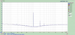
During amplifier testing I noticed the oscillator does not care to be loaded down with your circuit, so I put this signal into Pete Millet's soundcard interface, which has a gain of 2, and balanced line driver output.
Then I get 2nd at -122dB below fund, and 3rd at -131dB below fund. That's about 7 times as much distortion, but still quite usable for testing amps and preamps.
I can provide calculations if anyone questions my numbers, knowing the notch filter gains the 2nd by 31dB and the 3rd by 35dB.
Jensen transformer should be coming this afternoon, so I will get some readings to compare.
Attachments
@Samuel Groner -- I think that the lamp R was too small in any case to see the kind of issue that happened with the old HP200CD et al, which had lamps with *much* higher operating point resistances. Even so, I'm now not sure that any voltage coefficient effects could possibly be large enough, even at 10 or 20VRMS output to actually make a difference in stability. But it's an open question for now.
I've built several lamp-based "thermal" compressors for musical instrument use, there I noticed the mentioned slope of distortion, too. In fact I was exactly after that as a welcomed side-effect, the smaller the lamp's thermal inertia the higher the distortion (I used the smallest lamps comercially availabe, 1.2V/10mA, as well as big ones with several watts). I biased the lamps with DC right at their resistance knee, just below a visible red glow, this gave raise to strong second harmonic at very low frequencies and low levels which is what I wanted.
I also noted that a hot lamp must be well shielded from vibration (notably with DC bias it literally is a microphone) and I've seen this done in commercial lamp-stabilized oscillators by Grundig.
I also noted that a hot lamp must be well shielded from vibration (notably with DC bias it literally is a microphone) and I've seen this done in commercial lamp-stabilized oscillators by Grundig.
Last edited:
I've built several lamp-based "thermal" compressors for musical instrument use, there I noticed the mentioned slope of distortion, too. In fact I was exactly after that as a welcomed side-effect, the smaller the lamp's thermal inertia the higher the distortion (I used the smallest lamps comercially availabe, 1.2V/10mA, as well as big ones with several watts). I biased the lamps with DC right at their resistance knee, just below a visible red glow, this gave raise to strong second harmonic at very low frequencies and low levels which is what I wanted.
I also noted that a hot lamp must be well shielded from vibration (notably with DC bias it literally is a microphone) and I've seen this done in commercial lamp-stabilized oscillators by Grundig.
Hi KSTR,
Was this an optical coupling of the lamp or is the lamp in the amplifier circuit.
How did you isolated the DC bias from the amplifier? I would expect a strong dc offset in the amplifier from the bias.
The lamp was the actual passive "gain-cell", lamp as series resistor, another R to GND to form a divider. The bias current was injected with a floating current source accross the lamp, and the whole thing was AC-coupled at in and out driven by small pwr stages, also there were two of these cells in series to handle the dynamic range.
I'm aware this introduced additional effects from the biasing alone working back on the capacitors. An alternative would have been to use HF bias but that seemed unneccesary for the application (bass guitar amplifier) because a little "thumping" was not a problem there.
Using no bias didn't sound as good because the time constants and dynamic response was not optimum.
EDIT: and no 2nd harmonics, of course.
Last edited:
I might do this measurement. With full spectrum you mean DC to xxkHz, linear view? With or without fundamental notch?Yeah - I was wondering about Victor's phase noise and THD+N. A full spectrum comparison betweem AP's and Victor's would be interesting.
I might also scope the gate drive to see how much it fluctuates.
The lamp was the actual passive "gain-cell", lamp as series resistor, another R to GND to form a divider. The bias current was injected with a floating current source accross the lamp, and the whole thing was AC-coupled at in and out driven by small pwr stages, also there were two of these cells in series to handle the dynamic range.
I'm aware this introduced additional effects from the biasing alone working back on the capacitors. An alternative would have been to use HF bias but that seemed unneccesary for the application (bass guitar amplifier) because a little "thumping" was not a problem there.
Using no bias didn't sound as good because the time constants and dynamic response was not optimum.
EDIT: and no 2nd harmonics, of course.
So the idea was to add some 2nd H to the base. I presume this fattened up the base sound.
Is the AP oscillator stabilized (disciplined)? It shows less close in phase noise than Victors.
No. The sidebands are also affected from the amplitude leveling loop and the plain noise floor of the filter and multiplier (close to the fundamental frequency, noise gain get's very high).
Our AP is about two years old, is that late enough?
No idea, I don't have any details.
I might do this measurement. With full spectrum you mean DC to xxkHz, linear view? With or without fundamental notch?
To evaluate sideband performance I'm using these settings:
* Direct FFT (without notch--it would cut most of the sideband).
* Linear frequency scale, range about +-10% (or even just +-5%) of the fundamental (e.g. 900-1100 Hz).
* Amplitude range set such that most of the fundamental is chopped off, and the sidebands good visible.
* A FFT window with very good side lobe behaviour is important; IIRC the "equiripple" design is the best for the SYS-2722.
* Use the highest possible FFT resolution (32k) and lowest possible sampling rate to get the most narrow main lobe.
* Experiment with different average numbers--I've seen that for some oscillators the sideband noise drops with higher averages. I'm not sure what the exact mechanism is, but there is surely more going on than just plain "phase noise" as we know it from HF oscillators (e.g. there's also amplitude noise).
Samuel
I'm not sure what the exact mechanism is, but there is surely more going on than just plain "phase noise" as we know it from HF oscillators (e.g. there's also amplitude noise).
Samuel
Another observation on my impractical thermally stabilized oscillator experiment is that when it was stable the side bands virtually dissapeared.
Yes, I've observed too that low phase margin in the leveling loop leads to pronounced sidebands (also funny stuff like peaking a few Hz from the fundamental). On the other hand, I've found that loop compensation for optimum settling time is, most unfortunately, not the one for best sideband performance.
Samuel
Samuel
Yes, I've observed too that low phase margin in the leveling loop leads to pronounced sidebands (also funny stuff like peaking a few Hz from the fundamental).
A kind of very low level (and very low freq) amplitude modulation? I've seen it too, and spent quite a few hours before figuring out what the hell was going on
L.
- Home
- Design & Build
- Equipment & Tools
- Low-distortion Audio-range Oscillator