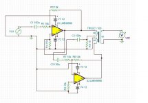
I made some changes to improve DC balance and reduce DC offset. I added C3 to block the DC offset of U1, and I increased R4 and added R5. DC offset on the outputs of both U1 and U2 are now the same at about 12uV. The value of R3 is a function of the specific transformer used. Bass response can be extended by careful selection of this resistor's value. If it's too high, then a really big resonant peak appears at less than 1Hz, whereas reducing it progressively reduces the peak to eventually a flat extended response with what appears to be a second order roll off. In simulation I changed it to 18 ohms and bass response extends to 4Hz.
Attachments
Last edited:
I wonder if something like this would work for this application.
The transformer would take the place of the ADC in this schematic.
David.
You can simulate it and find out, but I don't think the results will be better.
Speaking of the OPA1632, I I see that it can accept single ended or balanced inputs. I have the PCM4222EVM board from TI that uses this amplifier with XLR combi (accepts XLR or phone plugs) jacks on the board. Would you know how I would connect a single ended source to this board? Do I use a single ended phone plug? I'm lacking some information on this. Thanks.
Short the pin that connects to the inverting input to ground and your good to go.
David.
Why do designers put 2x1.0 kOhm resistors in series when a perfectly good 2.0 kOhm resistor is available?
Perhaps lower voltage and power coefficient (i.e. less distortion contribution from the resistor).
Samuel
You can simulate it and find out, but I don't think the results will be better.
Speaking of the OPA1632, I I see that it can accept single ended or balanced inputs. I have the PCM4222EVM board from TI that uses this amplifier with XLR combi (accepts XLR or phone plugs) jacks on the board. Would you know how I would connect a single ended source to this board? Do I use a single ended phone plug? I'm lacking some information on this. Thanks.
I'm not looking for better just simpler. If one IC can do it then it's better than two.
The standard is a regular phone jack shorts the inverting pin if they set it up this way.
David.
Last edited:
Loosing a half (3dB) of ADC's potential... I've shorted the pin to ground at RCA-XLR adapter i've made, at RCA's end - so i've got a bit of wire compensation.
Ah, that's a good idea, thanks.
How do I control the gain of this oscillator from Linear Technology? I just ordered the parts. I want to try it out, but I don't need 20V output!
Do I put an attenuator after the LT1029?
Add a passive attenuator, perhaps followed by a low-corruption buffer. The oscillator output level was probably engineered to be a particular value that balanced overall distortion against noise.How do I control the gain of this oscillator from Linear Technology? I just ordered the parts. I want to try it out, but I don't need 20V output!
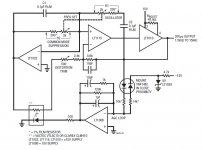
Changing the output level would require adjusting values in the temperature-compensated peak detector circuit (the two diodes that should be mounted in close proximity, the 5V "Zener", and the 10K and 14K 1% resistors). At first glance, the design seems rather straightforward (the two diodes carry equal average current at the designed output level) but I'd like to have that assumption confirmed before modifying the design. Does the associated AppNote mention anything about this piece of the circuit?
Dale
Add a passive attenuator, perhaps followed by a low-corruption buffer. The oscillator output level was probably engineered to be a particular value that balanced overall distortion against noise.
Changing the output level would require adjusting values in the temperature-compensated peak detector circuit (the two diodes that should be mounted in close proximity, the 5V "Zener", and the 10K and 14K 1% resistors). At first glance, the design seems rather straightforward (the two diodes carry equal average current at the designed output level) but I'd like to have that assumption confirmed before modifying the design. Does the associated AppNote mention anything about this piece of the circuit?
Dale
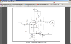
Thank you for looking at this for me. The link to the document is here:
http://cds.linear.com/docs/Application Note/an43f.pdf
page 33 has this particular figure.
Figures 43 and 45 show a similar schematic with a different reference, set at 1.2V and the output is 1Vrms, but the arrangement is different from figure 48.
I looked a little at the HP200 series oscillators and they seem to use an output attenuator, but I don't know for sure.
Last edited:
Now I feel like an idiot for ordering the parts for the LT oscillator that outputs 20V p-p. I wish I was smarter so I could modify this circuit for something more reasonable like 2Vrms output. I wanted something I could build myself. One thing I don't like about Victor's oscillator is the fact that there's no way to mount it without grounding it. I suppose I could use a piece of plastic but it just seems so cheap to do it that way. I've got a super duper box and I want to put something really professional inside of it. Sometimes I feel like I'm a chicken running around without a head...
Can I put an attenuator between the LT1115 and the output buffer LT1010?
oops, never mind. that won't work.
Can I put an attenuator between the LT1115 and the output buffer LT1010?
The LT1010 is very prone to high frequency oscillation. I had one oscillate near 100 MHz.
They work great if one uses what's outline in the data sheet.
David.
I use a Hammond aluminum enclosure, with surface mount terminal block going through holes in the side of the enclosure. +/-VDC power supply, +/- signal output, and an earth terminal which is bonded to the enclosure. Victor's oscillator is supported inside with standoffs epoxied to the enclosure (JB Weld) and then the PCB is glued to the standoffs in two places where there are no electrical connections to the circuit. That way the oscillator is securely mounted inside a metal enclosure, and the I/O is isolated from ground for a more or less balanced output. Works very well for low cost.One thing I don't like about Victor's oscillator is the fact that there's no way to mount it without grounding it. I suppose I could use a piece of plastic but it just seems so cheap to do it that way.
To keep the enclosure small, I did replace the carbon pot with a Bourns multiturn pot. That is also glued to the pcb with the adjustment screw pointing up. I remove the cover if I need to make adjustments (which I don't, it's just set for 2V output).
I can provide pictures if you need a better description. A little effort, but the oscillator operates so well it was hard not to make it work.
Without sitting down and actually THINKING about it (Thinking makes my brain hurt!), Fig 48 seems more intuitively straightforward than Fig 43 or Fig 45.Figures 43 and 45 show a similar schematic with a different reference, set at 1.2V and the output is 1Vrms, but the arrangement is different from figure 48.
If a lower output level is the main factor (disregarding noise performance), reduce the voltage rating of the LT1029. Something like the LT1034-1.2 should get you in the right range, then you can adjust the values of the 10K and 14K resistors to get the voltage you want. Increase the 10K or reduce the 14K to increase the output voltage; and vice-versa.Now I feel like an idiot for ordering the parts for the LT oscillator that outputs 20V p-p. I wish I was smarter so I could modify this circuit for something more reasonable like 2Vrms output.
Dale
Without sitting down and actually THINKING about it (Thinking makes my brain hurt!), Fig 48 seems more intuitively straightforward than Fig 43 or Fig 45.
If a lower output level is the main factor (disregarding noise performance), reduce the voltage rating of the LT1029. Something like the LT1034-1.2 should get you in the right range, then you can adjust the values of the 10K and 14K resistors to get the voltage you want. Increase the 10K or reduce the 14K to increase the output voltage; and vice-versa.
Dale
Yes, I am familiar with the brain hurting bit. I read the app note section on Wein bridge oscillators a couple of times and I still don't understand completely how this works.
OK, so I can replace the LT1029 with a lower reference voltage, and then alter the ratio of the 10k and 14k resistors to change the output. Maybe I can do that with a pot?
In my head, I have a nice single board with the variable frequency and output oscillator driving two single ended outputs, and also a pair of mixed feedback drivers for two transformer balanced outputs. This way, a stereo ADC can take one input directly from the oscillator, and the other input can come through the D.U.T. In the computer, I can do a L-R in the FFT and take out the distortion from the oscillator, leaving only the junk from the D.U.T.
The LT1010 is very prone to high frequency oscillation. I had one oscillate near 100 MHz.
They work great if one uses what's outline in the data sheet.
David.
OK, thanks for the warning.
- Home
- Design & Build
- Equipment & Tools
- Low-distortion Audio-range Oscillator