MPQ6842 is not easy to get:
MPQ6842 | EDX Electronics
Fixed-frequency ultra-low disto oscillator looks ok for this application.
MPQ6842 | EDX Electronics
Fixed-frequency ultra-low disto oscillator looks ok for this application.
I looked inside my Amber unit, it is a Bourns 4-gang pot, did not read the #'s but I think it is a 81/82 series pot, as found on the web site. Must be special order, or find 4 of them and stick some single units together as shown in the data sheet, good luck.
Hope I never have to fix that part.
The MPQ6542, near impossible to get, can be sub'd with I think DDMT5401/5551 duals, or some others, not sure if matching NPN & PNP's pairs is an issue.
Yes Victors fixed freq oscillator is the thing to make or buy from him. A few discrete frequencies is fine. It is a very good deal!! All good stuff to read.
Rick
Take a look at the Heath IG-18 I modded to Cordell's SV oscillator here: IG-18 #2, the BIG-18. The results are pretty good overall.
want to join in on this oscillator
I was not aware of this thread, only saw it now...
I also have researched for a while what the best oscillator may be to use. Some people here mentioned (now late) Jim Williams of Linear Systems but they looked too far back at his application notes. Look at AN132 yr2011 ( http://cds.linear.com/docs/Application Note/AN132f.pdf ) which originated with prof.Hill affiliated with Harvard and then was improved by Jim. I comunicated with the other two authors and gathered enough info to change dc offset and the frequency. I am only interested in one (around 2kHz), maybe two discrete frequency settings (2k and 10k) to take a measurement at.
I also have Gerber files for the pcbs. Only the parts are not cheap because they insist on Os-Con caps (brand name by sanyo), which I confirmed through private correspondence. I did not yet check into the availability of all the values since this is a lower priority project for me. If there were enough others to bring the pcb cost down maybe i would move on it quicker. Interested?
I do not believe anything else out there will beat this at 120dB signal S/N ratio.
I do not believe anything else out there will beat this at 120dB signal S/N ratio.
Do you mean THD+N? It seems that Williams' generator doesn't even get close to that figure, although -105 dB is certainly a respectable figure @ ~1.5 Vrms out. I think a state variable topology working at higher output may be better in this respect.
L.
Hi
we are using the 1KHz oscillator to test our AD7760 based function blocks, and we are seeing some problems, they may be related to the DC block capacitor but we are not sure yet. We made first measurements with 47uF MLCC capacitor (ouch !!! our bad of course) we got somewhat below 8ppm THD, 101 db SNR, with 3rd harmonic being dominating.
Replacing the DC block with some 0.33uF large ugly blue 1000V rated capacitor of unknown technology and origin, we got 5.3 ppm THD, 105 SNR, but we completely lost 3rd harmonics? At least below 145dB !!
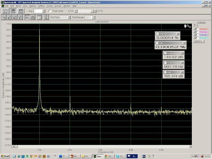
FFT attached, 1M point FFT, AD7760 with 625KSPS sampling rate default digital filters used (cut off 250KHz).
Can I assume safely that the 3rd harmonic what we did see with MLCC capacitor was indeed the capacitor non-linearity related spur?
In that case the 2nd harmonics that dominate with the other capacitor is most likely not any more at all related to the capacitor but some design problem with our ADC?
We do supply the 1KHz generator from four 9V batteries, output level is set to the maximum.
Any ideas how to get the remaining harmonics out? We will try more capacitors, but I bet those will not change the picture any more.
/Antti
we are using the 1KHz oscillator to test our AD7760 based function blocks, and we are seeing some problems, they may be related to the DC block capacitor but we are not sure yet. We made first measurements with 47uF MLCC capacitor (ouch !!! our bad of course) we got somewhat below 8ppm THD, 101 db SNR, with 3rd harmonic being dominating.
Replacing the DC block with some 0.33uF large ugly blue 1000V rated capacitor of unknown technology and origin, we got 5.3 ppm THD, 105 SNR, but we completely lost 3rd harmonics? At least below 145dB !!
FFT attached, 1M point FFT, AD7760 with 625KSPS sampling rate default digital filters used (cut off 250KHz).
Can I assume safely that the 3rd harmonic what we did see with MLCC capacitor was indeed the capacitor non-linearity related spur?
In that case the 2nd harmonics that dominate with the other capacitor is most likely not any more at all related to the capacitor but some design problem with our ADC?
We do supply the 1KHz generator from four 9V batteries, output level is set to the maximum.
Any ideas how to get the remaining harmonics out? We will try more capacitors, but I bet those will not change the picture any more.
/Antti
1) your ADC will never be perfect.
2) Ceramic caps will limit the performance a lot.
3) only a few types of film caps will be linear enough to not be an issue, Teflon, polystyrene and polypropylene are commonly available.
4) The AGC is the bigger issue in distortion at this level. The Silonex parts are good but CDSE is non-linear with a high voltage coefficient. Keep the voltage across it as small as possible.
5) Some opamps are potentially lower in distortion. It seems hard to predict and you will need to just measure the results.
6) Use a twin T notch to see what the source distortion is. I get well below -130 for all the harmonics with the Shibasoku generator so I know its possible.
7) When you get all the pieces working better you will see more things to make better. There is no end to this.
8) Victors oscillator is more than good enough for almost any kind of testing and costs so little for what it is.
Low Distortion Oscillator
Take a look at the Heath IG-18 I modded to Cordell's SV oscillator here: IG-18 #2, the BIG-18. The results are pretty good overall.
This get my vote!! Nice implementation. Forget the Amber unit, although you could borrow from some of the circuits it contains.
I wonder how using standard SMT passive parts, although good ones (only NPO & X7R), would affect the performance. I read that Victor changed from standard Yageo MF to some exotic Vishay parts & it made a difference?
Nice web site Mr. Moore, more to read and learn!! Now back to programming for my portable stereo unit!!
Cheers
Rick
Take a look at the Heath IG-18 I modded to Cordell's SV oscillator here: IG-18 #2, the BIG-18. The results are pretty good overall.
This get my vote!! Nice implementation. Forget the Amber unit, although you could borrow from some of the circuits it contains.
I wonder how using standard SMT passive parts, although good ones (only NPO & X7R), would affect the performance. I read that Victor changed from standard Yageo MF to some exotic Vishay parts & it made a difference?
Nice web site Mr. Moore, more to read and learn!! Now back to programming for my portable stereo unit!!
Cheers
Rick
I got the PCM4222EVM board yesterday. Just as I suspected, it was never intended to be put into a box. The board has rubber feet on it. One part at a time.... sigh.
I'm still waiting on the hi zoot 9V batteries and charger, and the parts for the CCS for Victor's oscillator. It's like watching grass grow.
I'm still waiting on the hi zoot 9V batteries and charger, and the parts for the CCS for Victor's oscillator. It's like watching grass grow.
1) your ADC will never be perfect.
2) Ceramic caps will limit the performance a lot.
3) only a few types of film caps will be linear enough to not be an issue, Teflon, polystyrene and polypropylene are commonly available.
4) The AGC is the bigger issue in distortion at this level. The Silonex parts are good but CDSE is non-linear with a high voltage coefficient. Keep the voltage across it as small as possible.
5) Some opamps are potentially lower in distortion. It seems hard to predict and you will need to just measure the results.
6) Use a twin T notch to see what the source distortion is. I get well below -130 for all the harmonics with the Shibasoku generator so I know its possible.
7) When you get all the pieces working better you will see more things to make better. There is no end to this.
8) Victors oscillator is more than good enough for almost any kind of testing and costs so little for what it is.
I am using Victors generator.. that is why I am wondering.. I am measuring Victors oscillator directly to the ADC, well, there is AD4940 before the ADC doing single ended to differential conversion..
If some one is looking for a pcb for the Jim Williams 10khz oscillator, i believe that Frex is still selling them. Just search for Username: Frex and Topic: oscillator .
The following link is mid point of the thread showing the performance. A few pages prior, I believe Frex posted his results.
http://www.diyaudio.com/forums/equipment-tools/160432-diy-analog-digital-converter-project-audio-measurements-tool-11.html
The following link is mid point of the thread showing the performance. A few pages prior, I believe Frex posted his results.
http://www.diyaudio.com/forums/equipment-tools/160432-diy-analog-digital-converter-project-audio-measurements-tool-11.html
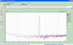
Here is the spectra from Frex
http://oneaudio.net/Pict/THDwithNotch.pdf
See post number 58 in previously posted thread.
http://oneaudio.net/Pict/THDwithNotch.pdf
See post number 58 in previously posted thread.
Last edited:
Victors 1KHz measurements, no notch method
Hi
after some fine tuning we got some pictures that look already pretty nice:
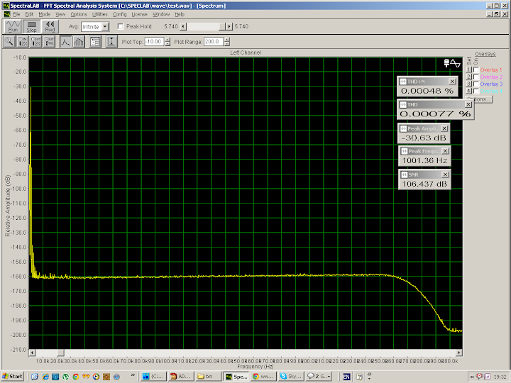
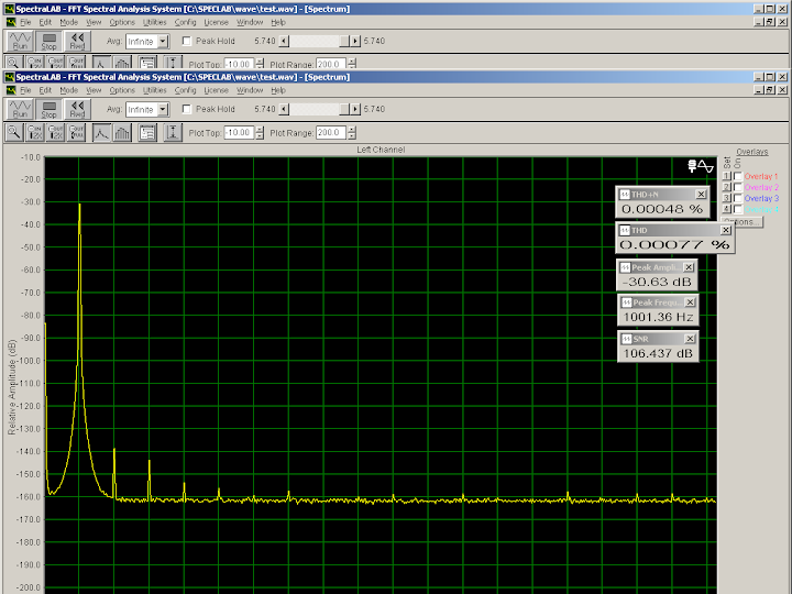
Both screens are from same FFT run, Blackman window, 65K points, sample rate is 625KHz. I guess those are not so bad plots for DIRECT without notch filter measurements.
Can someone comment if this is all that is possible, or would it be really possible to get rid of the last harmonics spurs?
Setup: Victors oscillator (batterie powered) > DC coupled to AD4940 +input, AD4940 -input to GND via 620 Ohm, AD4940 OCM floating (Decoupled with 0.1uF to GND). ADC is AD7760. Victors oscillator is not shielded just PCB.
To have on the desk an ADC with 160dB noise floor is already nice, but we want more") to get rid of the last few ppm of THD.
to get rid of the last few ppm of THD.
As of ALL measurements done with Victors generator, the spurs of 2nd and 3rd harmonic what we see at -138dB and -143dB are not in the generated signal?
Ok, we still have some fine tuning todo, the resistors in the differential path are maybe not all 0.1% ones and the power supply for AD4940 is a bit asymmetrical (+3V and -3V).
BTW, we will maybe be doing replica of the claimed PPB range oscillator, the funky one with those 180dB gain blocks.
I wonder if anyone has any experience with that design?
Its the Figure 67 in LT appnote collection AN67F
Hi
after some fine tuning we got some pictures that look already pretty nice:
Both screens are from same FFT run, Blackman window, 65K points, sample rate is 625KHz. I guess those are not so bad plots for DIRECT without notch filter measurements.
Can someone comment if this is all that is possible, or would it be really possible to get rid of the last harmonics spurs?
Setup: Victors oscillator (batterie powered) > DC coupled to AD4940 +input, AD4940 -input to GND via 620 Ohm, AD4940 OCM floating (Decoupled with 0.1uF to GND). ADC is AD7760. Victors oscillator is not shielded just PCB.
To have on the desk an ADC with 160dB noise floor is already nice, but we want more
to get rid of the last few ppm of THD. As of ALL measurements done with Victors generator, the spurs of 2nd and 3rd harmonic what we see at -138dB and -143dB are not in the generated signal?
Ok, we still have some fine tuning todo, the resistors in the differential path are maybe not all 0.1% ones and the power supply for AD4940 is a bit asymmetrical (+3V and -3V).
BTW, we will maybe be doing replica of the claimed PPB range oscillator, the funky one with those 180dB gain blocks.
I wonder if anyone has any experience with that design?
Its the Figure 67 in LT appnote collection AN67F
Hi
after some fine tuning we got some pictures that look already pretty nice:
Both screens are from same FFT run, Blackman window, 65K points, sample rate is 625KHz. I guess those are not so bad plots for DIRECT without notch filter measurements.
Can someone comment if this is all that is possible, or would it be really possible to get rid of the last harmonics spurs?
Setup: Victors oscillator (batterie powered) > DC coupled to AD4940 +input, AD4940 -input to GND via 620 Ohm, AD4940 OCM floating (Decoupled with 0.1uF to GND). ADC is AD7760. Victors oscillator is not shielded just PCB.
To have on the desk an ADC with 160dB noise floor is already nice, but we want more
As of ALL measurements done with Victors generator, the spurs of 2nd and 3rd harmonic what we see at -138dB and -143dB are not in the generated signal?
Ok, we still have some fine tuning todo, the resistors in the differential path are maybe not all 0.1% ones and the power supply for AD4940 is a bit asymmetrical (+3V and -3V).
BTW, we will maybe be doing replica of the claimed PPB range oscillator, the funky one with those 180dB gain blocks.
I wonder if anyone has any experience with that design?
Its the Figure 67 in LT appnote collection AN67F
I believe Jackinnj has quite a bit of experience with the one with the 180dB blocks.
I don't remember the thread but he did build this and analyze it with comparison to other oscillators. If you do a search I think you can find the thread.
"the spurs of 2nd and 3rd harmonic what we see at -138dB and -143dB are not in the generated signal?"
If these are not in the generated signal then where are they coming from?
I wonder if notching the fundamental would reduce this.
David.
Hi
after some fine tuning we got some pictures that look already pretty nice:
Both screens are from same FFT run, Blackman window, 65K points, sample rate is 625KHz. I guess those are not so bad plots for DIRECT without notch filter measurements.
Can someone comment if this is all that is possible, or would it be really possible to get rid of the last harmonics spurs?
Setup: Victors oscillator (batterie powered) > DC coupled to AD4940 +input, AD4940 -input to GND via 620 Ohm, AD4940 OCM floating (Decoupled with 0.1uF to GND). ADC is AD7760. Victors oscillator is not shielded just PCB.
To have on the desk an ADC with 160dB noise floor is already nice, but we want more
As of ALL measurements done with Victors generator, the spurs of 2nd and 3rd harmonic what we see at -138dB and -143dB are not in the generated signal?
Ok, we still have some fine tuning todo, the resistors in the differential path are maybe not all 0.1% ones and the power supply for AD4940 is a bit asymmetrical (+3V and -3V).
BTW, we will maybe be doing replica of the claimed PPB range oscillator, the funky one with those 180dB gain blocks.
I wonder if anyone has any experience with that design?
Its the Figure 67 in LT appnote collection AN67F
Hi trioflex,
I can't find a part for an AD4940. Do you mean ADA4940?
http://www.analog.com/static/imported-files/data_sheets/ADA4940-1_4940-2.pdf
David.
Hi trioflex,
I can't find a part for an AD4940. Do you mean ADA4940?
http://www.analog.com/static/imported-files/data_sheets/ADA4940-1_4940-2.pdf
David.
Hi
sorry yes ADA4940 this looks like the BEST available part to perform single ended to differential conversion, this is the only reason we use it, we do not need to change the common mode level, as AD7760 already is centered around 0V using the on-chip differential amplifier.
If there exist better IC to do low noise, low distortion we would sure consider using other part, but well we need bandwidth up to 1MHz, this is a bit above audio band..
Issues problems we have, maybe: AD7760 has 680 ohms all resistors on the differential ampliefier, so its input impedance bit above 680 ohm, now we accidentially have 549 ohm series with 51pF to GND after ADA4940, this not right of course the 549 ohm is too large there, but that only explains some extra attenuation we see on fundamental signal.
What is maybe bigger problem is that ADA4940 has about 260 ohms input impedance, and this is connected directly to Victors oscillator, well the oscillator has 600 ohm series, and it should I think work pretty well with low impedance loads too. But for sure oscillator output impedance is higher then ADA4940 input. ADA4940 has 1.2nF in parallel to the feedback resistor, so basically Victors oscillator is loaded with 200 ohm in series with 1.2nF.
Where do the harmonics come? This is to be found out.. When trying out Analog devices Differential Opamp calculator tool we see that ADA4940 with with the settings we are using should have SNR of around 105dB, well we are measuring SNR 106 for complete setup that includes ADA4940.
What is a bit mystery is that we have seen 3rd harmonics COMPLETLY disappearing in output spectrum! This was when we used 0.33uF large T/H capacitor as DC block in the oscillator output. 47uF MLCC 1206 added 5 db to the SNR, and 0.33uF DC bloc did hide the second harmonic into 150dB noise floor! If Victors oscillator would have 3rd harmonic present (at measurable with our system levels) would DC block capacitor type change be able to push 3rd harmonics (but only 3rd) down by 20+ dB?
Ah stupid, it is probably related to the loading of the oscillator!
Ok, the last 2 FFT plots are done with DC coupled measurement, without block capacitor, full path from oscillator to the ADC is DC coupled.
Why don't you bypass the single ended to diff converter for the test? You can take the oscillator output through a series divider with the cenert tap tied to ground. With battery power it can work pretty well. put the oscillator in a metal box and tie the box to the center tap. Tie that point to the bias for the inputs of the ADC.
I published what I got for Victors oscillator earlier in the thread. All the harmonics were less than -110 as I remember.
THAT has some very good single ended to diff converters and vice versa. Certainly worth looking at.
At these levels the phase relationships of the harmonics generated can cause odd things like cancellation to happen. Also dropping the level into the ADC by 1-2 dB can reduce the harmonics a lot.
Hi
well, initially we had the ADA4940 bypassed. We did see some very bad signal, well the best we did see was fundamental 20dB below noise! While troubleshooting this problem we installed the ADA4940 SMD module to the test base board we use. After 3 days of troubleshooting with Logic analyzer and VHDL simulations we found that the problem we did witness (signal below noise) was because in the GUI visualization software, well not even sure what was wrong, but I can tell what we changed to make it all work: We changed the size of the read buffer where we did take the samples for oscilloscope display. We did not change any functional code. The results we started to see then looked already very promising.
Taking the ADA4940 differential conversion out is possible but due to the small thermal resistance, we would have to PREHEAT the baseboard in order to suck off some solder from the pads that connect ADC module to the ADA4940 module.
AD7760 module uses 0201 components and well cost a bit, so we do not want to solder and re-solder too many times.
We can connect victors oscillator directly to ADC + input and tie -input to ground. This is acceptable (with 6dB performance loss). Of course when powered from battery, the trick with divider center point would work as well.
Harmonics are down almost 110 dB in our measurements already, I am hunting for 20dB more... as per measurements Victors oscillator it should be possible? The best THD reading we got was 5.3 ppm, Victors oscillator has been measured to be below 0.3 ppm. So we would love to see our ADC to actually measure below 1 ppm
- Home
- Design & Build
- Equipment & Tools
- Low-distortion Audio-range Oscillator