Bruel & Kjaer 1607 Twin Tee
I finally dug this rare (and important antique) out of storage and checked to see if it would work. it does and it gives some verification of the performance of the oscillator.
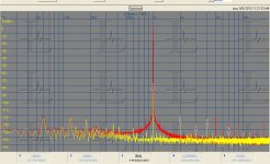
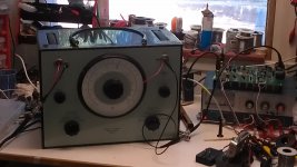
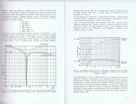
The spectrum shows the un-notched as the red trace and the notched as the yellow. Also is a picture of it in use (not the best lab technique) and a page from the manual showing its notch characteristics. The manual does not have the circuit (a first for B&K manuals of that vintage) so I may need to reverse engineer it. Also a clean mod to work around the B&K connectors is on my to-do list.
I finally dug this rare (and important antique) out of storage and checked to see if it would work. it does and it gives some verification of the performance of the oscillator.
The spectrum shows the un-notched as the red trace and the notched as the yellow. Also is a picture of it in use (not the best lab technique) and a page from the manual showing its notch characteristics. The manual does not have the circuit (a first for B&K manuals of that vintage) so I may need to reverse engineer it. Also a clean mod to work around the B&K connectors is on my to-do list.
Attachments
For lower jitter i'd guess")
I would think it would be easier to just replace one of the on board clocks. It's just solder.... I don't know enough to know if that's a good idea.
I finally dug this rare (and important antique) out of storage and checked to see if it would work. it does and it gives some verification of the performance of the oscillator.
The spectrum shows the un-notched as the red trace and the notched as the yellow. Also is a picture of it in use (not the best lab technique) and a page from the manual showing its notch characteristics. The manual does not have the circuit (a first for B&K manuals of that vintage) so I may need to reverse engineer it. Also a clean mod to work around the B&K connectors is on my to-do list.
Thats great -- just what I would need to use
For lower jitter i'd guess
Low jitter is the primary issue. The TI board is pretty good while the AKM is a demonstration of why you don't want an inverter crystal oscillator. I am using an external OXCO (it draws as much as 12W) to get a low jitter clock. Its possible to get similar performance from the Crystek oscillators, but you do need to clean up the power supply.
Low jitter is the primary issue. The TI board is pretty good while the AKM is a demonstration of why you don't want an inverter crystal oscillator. I am using an external OXCO (it draws as much as 12W) to get a low jitter clock. Its possible to get similar performance from the Crystek oscillators, but you do need to clean up the power supply.
I'm up for modifying the TI board if someone can show me what needs to be replaced.
I'm expecting the parts for the CCS for my battery powered Victor oscillator pretty soon. I'm using the DN2540 mosfet in a cascode arrangement with the LM117 regulator, according to Walt Jung's design. I hope to have it up this weekend if I get my parts.
Victor also makes a 10kHz oscillator. Is it as good as the 1k variety?
Forgive me if this has been asked already, or that I don't understand, but can an active peak filter be used (tuned to a desired frequency) to reduce THD? I realize the active filter will introduce some distortion, but if the Q is high enough won't the net result be lower distortion? Is this idea already built into these low distortion oscillators? (I guess "peak filter" is an old fashioned term. I guess what I mean is a narrow bandpass filter)
Last edited:
An active filter is limited by its amplifier and in most implementations by the common mode non-linearity of the input of the opamp. A passive low pass filter is really the only way to improves on one of the really low distortion sources. And at these levels non-linearity of passive components may be the limiting factor.
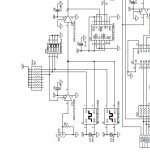
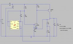
The TI board has two crystal oscillators with about the same foot print as the Crystek oscillators. They are on the attached schematic. You do need to improve the power supply to get the best results. I have attached an ultra low noise supply I created for this task that works quite well. The sim should open in LTspice with no fiddling.
The shunt regulators for Victors oscillators are set to 15V ea. Once the batteries drop below 15V the system will shift. Most likely the output voltage will drop and eventually the batteries will be drained. Adding batteries will only sell batteries, no change in performance. Adding a cascode may not help and may require more voltage to get to the same place.
Attachments
Can an active peak filter be used (tuned to a desired frequency) to reduce THD? I realize the active filter will introduce some distortion, but if the Q is high enough won't the net result be lower distortion? Is this idea already built into these low distortion oscillators? (I guess "peak filter" is an old fashioned term. I guess what I mean is a narrow bandpass filter.)
In general, the distortion of the filter swamps the distortion of the very-low distortion oscillator.
Oscillators are basically 2nd order filters (tuned to infinite Q). So the fundamental distortion limit from the amplifiers and passives of an additional filter stage is the same as for the basic oscillator alone. However, an additional low-pass filter (a bandpass seems unnecessary) can reduce the distortion contribution from the multiplier and from level detector ripple.
SRS DS360 (DS360 - Low Distortion Function Generator) uses such a filter, although the source in this case is a DAC, and overall distortion performance is not state of the art.
It is possible to use LC passive filters to do what you suggest, but that's really only practical for fixed frequency oscillators.
A passive low pass filter is really the only way to improve on one of the really low distortion sources.
I doubt that, at audio frequencies, a passive LCR filter would provide lower distortion than a decent active filter, as inductors are notoriously nonlinear. Using composite opamps, or high-performance discrete implementations, the distortion performance of the filter is easily pushed to a level where the passives and layout effects dominate. Not saying this is something for the casual designer, though.
Passive filters are used in the MHz region, but this is another matter...
An active filter is limited by its amplifier and in most implementations by the common mode non-linearity of the input of the opamp.
Of course one'd use a suitable filter topology, e.g. multiple feedback.
Samuel
Normally I would agree that inductors would limit what can be done. However the lowest distortion system I have, the Radiometer CLT-1, uses sophisticated LC filters with large Ferrite cores to make a -170 dB source. I have no idea how to duplicate those inductors and would not suggest that its an easy task. At -130 to -140 dB harmonics from the oscillators as they are I don't see a reason to try to improve on them. These are numbers that even the Halcro amps couldn't achieve.
Yes, I'm aware of the CLT1 (current version CLT10). The spec sheet says -150 dB guaranteed, -160 dB typical--where does your -170 dB come from? The secrets of it is probably revealed in their patents; I have yet to give them a detailed read.
Doesn't however convince me that an active filter wouldn't be the better (or at least easier) approach for a general-purpose bench oscillator.
Samuel
Doesn't however convince me that an active filter wouldn't be the better (or at least easier) approach for a general-purpose bench oscillator.
Samuel
Yes, I'm aware of the CLT1 (current version CLT10). The spec sheet says -150 dB guaranteed, -160 dB typical--where does your -170 dB come from? The secrets of it is probably revealed in their patents; I have yet to give them a detailed read.Samuel
Just reading the meters on the front. Only certain combinations of settings get there. And not necessarily under load. But it will deliver more than 1 watt into the DUT.
can an HP339A distortion analyzer be tweaked for lower thd measurment? Oh, say by anouther 20dB? And, if so - how? Thx - RNM
If I remember well the venerable 339A employs a Bridged-T active notch with auto tuning/nulling circuitry based on LDR/LED optocouplers, which are likely to be the responsible for the analyser residuals - imho if you're going to measure THD in the -120 dBc range (or less) it's better you build your own tool.
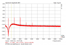
My favourite one is a manual-tuned double notch based on Bainter topology - a sample run of a 239A clone thru the notch is attached: @ +40 dB post notch gain noise floor is quite low, and you can easily (and stably) get more than 100 dB fundamental suppression - I'll post the schematics when I'll find it...
L.
Attachments
Yes, I'm aware of the CLT1 (current version CLT10). The spec sheet says -150 dB guaranteed, -160 dB typical--where does your -170 dB come from? The secrets of it is probably revealed in their patents; I have yet to give them a detailed read.
Samuel, just for the sake of curiosity: on what concepts this beast is based on?
L.
On what concepts this beast is based on?
I haven't studied the details enough to give a competent answer. Right now I can't find the patents with all the details, I think I have them at work. As far as I can tell from the information available at the manufacturers website (Danbridge), they use a tuned LC network which has very high output Z at 30 kHz (the 3rd harmonic of the used 10 kHz fundamental). This inherently prohibits any 3rd harmonic to flow into the load.
Note that this is not a general-purpose distortion analyzer; it can just analyze two-ports (in particular passives), and it's just the 3rd harmonic residual which is extremely low (and not e.g. the 2nd). One could imagine adapting this for a normal low distortion oscillator, and making the tuned network switchable between 2nd and 3rd harmonic reduction. But this sounds like a tremendously complicated undertaking...
Samuel
Last edited:
- Home
- Design & Build
- Equipment & Tools
- Low-distortion Audio-range Oscillator