I used the oscillator to help with designing and building a very cheap distortion analyser with an unusual technique, working at zero frequency - much easier to get a bandwidth of a few Hertz than at higher frequency where you require crystal filters. I think it worked quite well; I took out a provisional patent for some of the techniques but never quite completed the project, deciding there was no market, or at any rate it wouldn't help me much in making a living. I have the prototype, but all paperwork, including circuit, has gone; I don't even know if I would remember how to use it. The idea came from a suggestion in M G Scroggie's Radio Laboratory Handbook. It did give readings, harmonic by harmonic, from the low-distortion oscillator - it was sensitive enough. Nowadays you'd probably do better with a good computer sound card and software to generate waves and analyse them.
Your design seems very close the ShibaSoku 725 distortion analyzer, which seems to hold the current record for lowest residual distortion. Certainly their oscillators are exceptional, possibly 20 dB better distortion than my KH4400.
I think its an excellent solution and will outperform a soundcard. All of this is academic given real world performance of real circuits.
For the state variable oscillator you learn a lot looking at existing solutions. The KH4402 and its older all discrete variants all have selectable time constants for the AGC loop that track the frequency range. The similar circuits in the Boonton 1120 use the microcontroller to manage AGC time constants and a lot of other aspects, including PLL'ing the frequency.
If interested I can post the schematics of the relevant circuits.
Selectable time constants in the oscillator AGC really do improve matters a lot. That's what I used in my distortion analyzer that I did about 30 years ago. Each decade range gets its own time constant. I also used speedup diodes in the AGC loop, which also helped helped tremendously with settling time for a given AGC filter bandwidth.
I also used range-dependent residual filtering to further improve performance by limiting the residual bandwidth to 10 times that of the fundamental frequency. The slectable residual filters also cut some of the frequency band below the fundamental. Some analyzers have a fixed 80 kHz HF cutoff, which unfortunately obscures upper harmonics for 20 kHz THD.
What is the residual of the ShibaSoku 725 at 20kHz and with what residual bandwidth?
Cheers,
Bob
If interested I can post the schematics of the relevant circuits.[/QUOTE said:Hi Audio1,
I'd like to have a look at the ShibaSoku 725 distortion analyzer. If you can post anything on that.
Cheers,
David.
I don't have the schematics for the 725, I have not been motivated to buy the manual yet since its all working.
What I was offering were schematics for the Boonton and the KH4400.
The residual distortion of the AG15C is rated as less than -120 dB (.0001%) and I measured it with the 725 as more like .00006 or less but at that point I'm not sure what I have since it measures differently, more like a lock in amplifier than a conventional distortion analyzer.
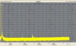
Looking at the output of the AG16 I have with an AKM AK5394a demo board there are no distortion artifacts above -126 dB at 12 KHz on the attached plot. This demo board has JRC5534's on its input. Its very useful to have a source this clean when you have questions about intrinsic distortion.
What I was offering were schematics for the Boonton and the KH4400.
The residual distortion of the AG15C is rated as less than -120 dB (.0001%) and I measured it with the 725 as more like .00006 or less but at that point I'm not sure what I have since it measures differently, more like a lock in amplifier than a conventional distortion analyzer.
Looking at the output of the AG16 I have with an AKM AK5394a demo board there are no distortion artifacts above -126 dB at 12 KHz on the attached plot. This demo board has JRC5534's on its input. Its very useful to have a source this clean when you have questions about intrinsic distortion.
Attachments
I don't have the schematics for the 725, I have not been motivated to buy the manual yet since its all working.
What I was offering were schematics for the Boonton and the KH4400.
The residual distortion of the AG15C is rated as less than -120 dB (.0001%) and I measured it with the 725 as more like .00006 or less but at that point I'm not sure what I have since it measures differently, more like a lock in amplifier than a conventional distortion analyzer.
Looking at the output of the AG16 I have with an AKM AK5394a demo board there are no distortion artifacts above -126 dB at 12 KHz on the attached plot. This demo board has JRC5534's on its input. Its very useful to have a source this clean when you have questions about intrinsic distortion.
Very nice. I'll do some digging for docs.
David.
Thanks very much for the response to my posting:
Unfortunately I'm quite out of it; this was done many years ago, and I don't even remember enough to discuss details sensibly. I see others have asked for details, so I'll have a look at them, but don't expect to have anything useful to contribute.
Your design seems very close the ShibaSoku 725...
If interested I can post the schematics of the relevant circuits.
Unfortunately I'm quite out of it; this was done many years ago, and I don't even remember enough to discuss details sensibly. I see others have asked for details, so I'll have a look at them, but don't expect to have anything useful to contribute.
Your design seems very close the ShibaSoku 725 distortion analyzer, which seems to hold the current record for lowest residual distortion. Certainly their oscillators are exceptional, possibly 20 dB better distortion than my KH4400.
Mixing down to DC? Our ShibaSoku is MIA, I wonder if metrology still has the manual in a file somewhere. I sort of gave up on this stuff when I realized that the null technique (Cordell or similar) gives me most of the information I need. Measuring passives to -140dBc is purely academic to me.
Last edited:
Mixing down to DC? Our ShibaSoku is MIA, I wonder if metrology still has the manual in a file somewhere. I sort of gave up on this stuff when I realized that the null technique (Cordell or similar) gives me most of the information I need. Measuring passives to -140dBc is purely academic to me.
Geeze, I hope it isn't the one I bought surplus a few years ago.
I use a Boonton 1120 on the bench since its faster to use and the performance is adequate to anything in the real world.
I use the Radiometer Copenhagen CLT-1 to measure passives since -140 dB is not nearly enough. -165 dB is just barely enough for most parts. Bad ones light up but good film resistors get close to -160 easily, wirewound and metal foil are essentially perfect. Look elsewhere for these problems (the thermal issues are significant however.)
If you do find manuals for the 725 and the associated oscillators, there are several, I'm very interested.
Here is a oscillator with THD bellow -140 dB.
Low distortion oscillator tests measurement circuits - 2012-05-03 04:33:52 | Test & Measurement World
Low distortion oscillator tests measurement circuits - 2012-05-03 04:33:52 | Test & Measurement World
Thanks Frex
It was the other diode beside D2 that puzzled me. I hadn't realised that the BAV99 is in fact a pair of diodes, and that leaves one half left over.
So that then raises the question, why choose a BAV99 if you only need a single diode? What characteristics of the BAV99 recommend it for use here?
Terry
Just completed a build of the oscillator in post #169. Note there are a few errors in the schematic in case you are interested in building- there is a node on either side of the photoresistor; it's not clear from the drawing. Also, the R-C values are for a 200Hz frequency, instead of 2kHz. I changed the caps to 10nF to compensate. Also pulling a little extra current through the TL431 for better compensation against leakage in the integrator feedback path. Based on an email from the author, I decreased the 47uF cap in the IC4 feedback path to 10uF. Using 15V series regulators in place of the zeners.
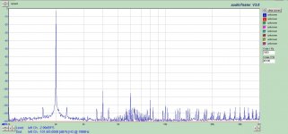
Anyways, my FFT is attached, and it is disappointing. Hopefully someone can help with the clear and obvious amplitude modulation. I was very careful to hand select resistors and capacitors for a nearly perfect (as accurate as I can measure) frequency matching between R-C-1 and R-C-2. I can even see the AM with the Fluke multimeter on the output.
Distortion and sidebands as shown in the original article are extremely low, so either the article is misleading or I am doing something very wrong. I have played around with the R and C values in the integrator, with essentially little effect. I know my soundcard is capable of much more, as the output of my DCX is much better than what is shown here.
Any gurus in PID control systems? As I read through this thread it seems the integrator is the weak link in the overall THD result.
Attachments
What do you see when you look at TP1 with a CRO? I imagine it will confirm that the negative feedback loop is hunting. We may learn something from the waveform there.
Also what's the oscillator's output swing (Vpk to pk)?
If you laid out a PCB, let us have a look at the layout. It's easier for other eyes to spot the obvious mistake than your own!
Terry
Also what's the oscillator's output swing (Vpk to pk)?
If you laid out a PCB, let us have a look at the layout. It's easier for other eyes to spot the obvious mistake than your own!
Terry
First: How are you measuring the THD? -100 dB is pretty good for most audio cards. Without a twin tee or the like few audio cards will see the distortion floor of an oscillator like this.
Second: I spent many days trying to duplicate Jim Williams low distortion oscillator he claimed to get running in an afternoon. I finally gave up. I could not get anything like his performance. These things often look too simple and are much more tweaky that they look.
Third: If you are getting amplitude modulation the AGC may have too much gain. Its oscillating at a low frequency. The LDR is a non linear device with a long, nonlinear time constant. It turns on much faster than it turns off. First, try to keep the voltage across it low. The distortion increases quickly as the voltage across it increases. That means the led is on the very on. Second you want to reduce the gain on the opamp comparing the reference voltage to the rectified peaks.
Starting with adjustment there are two pots, the one in series with the LDR sets the drive point of the ldr to meet the conditions of oscillation. If the system is too prone to oscillate then the ldr will be almost dark and most likely to hunt. Start with the pot at max and the LED drive will be highest to get oscillation going. If it doesn't oscillate and the led drive is max reduce the resistor until it does oscillate. The use the level adjust to set the output level.
The integrator is always a difficult problem. The commercial ones often use sample and hold systems to capture the peak voltage on every cycle. Cordell used a great trick to double the number of peaks per cycle that speeds settling time and does not require a sample and hold. The ripple on the integrator can feedback and add second harmonic (and sometimes reduce it).
Thanks for building the circuit and posting the test results.
I am not a guru in PID systems unfortunately and have tried to analyze the loop stability of an Oscillator but my differential equation skills aren't good enough. I used a sample and hold circuit to try to meet the conflicting requirements of no delay in the control circuit for stability along with low ripple.
The FFT plot shows mainly even hamonics which could be due to the photcell as well as the integrator.
Wow, thanks for the replies. I have a little work to do in order to answer some of your questions, so give me a little time. A few basic answers for now-
Pot is adjusted to provide for 10mA LED current, per the author. I did adjust this from 5mA to 15mA, with no discernible difference in modulation.
Output swing is adjustable from 2.2 to 4V RMS. Again, no difference in modulation with output swing.
Photoresistor has around 15mV across it, as it is in parallel with a 15 ohm resistor. Sounds fairly low to me.
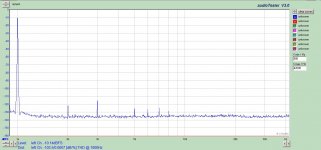
Attached is what I am trying to improve on- output of my DCX2496 with digital in, transformer coupled out. My sound card is quite repeatable with these measurements, so at this point I trust it.
Pot is adjusted to provide for 10mA LED current, per the author. I did adjust this from 5mA to 15mA, with no discernible difference in modulation.
Output swing is adjustable from 2.2 to 4V RMS. Again, no difference in modulation with output swing.
Photoresistor has around 15mV across it, as it is in parallel with a 15 ohm resistor. Sounds fairly low to me.
Attached is what I am trying to improve on- output of my DCX2496 with digital in, transformer coupled out. My sound card is quite repeatable with these measurements, so at this point I trust it.
Attachments
")
- Home
- Design & Build
- Equipment & Tools
- Low-distortion Audio-range Oscillator