Hi PChi,
I took too quick a look")
Anyway, the best way to achieve both high acquisition speed and low droop is employing a two stage peak detector, i.e. cascading a track&hold and a sample&hold, or two sample&hold - this way you may have the first stage optmized for speed and the second for accuracy. Take a look at the December 1985 issue of the HP Journal, in which you can find a description of the audio modulation section of the HP8642 RF generator (which is a true fast-settling, low THD BF generator). The same topology has been employed by HP itself in the 8903, and by AP and Boonton - I've tried it, and it actually works quite well. At first I tried the all-monolithic way via a pair of LF398, but did end up with a cascade of two open-loop discrete S&H (each consisting of a pair of buffers and a jfet) - I've found out that open-loop S&H are less DC-accurate than closed loop ones, but they are faster and more ripple-free. The zero-crossing detector is a LM311, and the S&H are driven by a bunch of hex inverters plus pair of bjt each; the first S&H actually tracks the signal from the negative peak to the positive one, and the second samples peak value for a fixed - small - amount of time. I'm not completely satisfied with this design (have to try a real peak-detector with reset in place of the first T&H - I hope this will further lower ripple), nevertheless it rocks.
L.
I took too quick a look
Anyway, the best way to achieve both high acquisition speed and low droop is employing a two stage peak detector, i.e. cascading a track&hold and a sample&hold, or two sample&hold - this way you may have the first stage optmized for speed and the second for accuracy. Take a look at the December 1985 issue of the HP Journal, in which you can find a description of the audio modulation section of the HP8642 RF generator (which is a true fast-settling, low THD BF generator). The same topology has been employed by HP itself in the 8903, and by AP and Boonton - I've tried it, and it actually works quite well. At first I tried the all-monolithic way via a pair of LF398, but did end up with a cascade of two open-loop discrete S&H (each consisting of a pair of buffers and a jfet) - I've found out that open-loop S&H are less DC-accurate than closed loop ones, but they are faster and more ripple-free. The zero-crossing detector is a LM311, and the S&H are driven by a bunch of hex inverters plus pair of bjt each; the first S&H actually tracks the signal from the negative peak to the positive one, and the second samples peak value for a fixed - small - amount of time. I'm not completely satisfied with this design (have to try a real peak-detector with reset in place of the first T&H - I hope this will further lower ripple), nevertheless it rocks.
L.
Hi L.
Thanks for informing me about the December 1985 issue of the HP Journal. I wasn't aware of it.
I have an oscillator based on the state variable / quadrature architecture of the type that is described in the HP Journal I used analogue multipliers to square the Integrator 'Sine' and 'Cosine' outputs and then combined them to produce a relatively low ripple control voltage. It's fast settling but not low distortion at about 0.2 % at 1 kHz. The state variable oscillator works well but I don't know how much the gain varies with frequency setting with the matching of a typical dual ganged potentiometer. That's why I chose the All Pass Filter circuit. Possibly not the best choice though.
I have been looking at reed relays, digital potentiometers and Multiplying DACs because the PCB mounted switches and potentiometers that I used are so expensive.
It's a pity that there are so few sample and hold options apart from the LF398.
Regards Paul
Hi David,
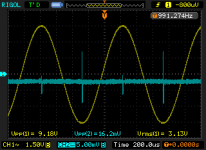
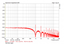
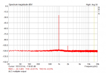
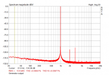
I've attached difference amplifier output as it appears both on the scope and in the spectrum analyzer; the 3rd graph shows ALC multiplier output, while the last one is the generator output itself scaled down to 1Vrms or so. I think T&H/S&H output ripple can be further reduced by replacing the first T&H with a true peak detector with reset, and maybe optimizing somewhat the layout (although I'm already employing local regulators and careful decoupling for both the ring itself and the peak detector), but what does actually matter is the analog multipler output signal, and it is quite clean, as you can see. This generator is based on a ring of 318s and a single AD633 in the ALC loop working at a decoupling factor of about 21, or 26.5dB; its unloaded output level is about 9.1Vpp - the operating Q @ 1kHz is slightly more than 60dB, and it runs smoothly from 10Hz to 150kHz (although its Q lowers quite a bit at high frequencies). It's a little bit noisier than the version with 2 AD633 and a 4-phase rectifier, but 318s are noisier than 5534s; anyway it seems to have quite a bit lower THD - something in the -130dBc range @1kHz, but I still have to check thoroughly these preliminary results - I know they are a little bit impressive...
Ciao,
L.
Attachments
Last edited:
I was looking at that 12-position 2-pole switch, and was wondering about adding a third pole to switch in different values for the sample-and-hold capacitor along with the oscillator capacitors. With relays and appropriate steering logic (diodes), you'd only need three or four extra relays to switch in several s/h caps so each works over a 10 to 1 range, as opposed to the current 1000+ to 1 range of a single capacitor. Reading about the sample time, you could increase and decrease it as well along with switching the capacitor.I have been looking at reed relays, digital potentiometers and Multiplying DACs because the PCB mounted switches and potentiometers that I used are so expensive.
It's a pity that there are so few sample and hold options apart from the LF398.
Regards Paul
Ho PChi,
You may also want to have a look at the August 1980 issue - it's entirely devoted to the venerable 8903 THD analyzer, and it's well worth a careful read.
Ciao,
Luca
Hi L.
Thanks for informing me about the December 1985 issue of the HP Journal. I wasn't aware of it.
You may also want to have a look at the August 1980 issue - it's entirely devoted to the venerable 8903 THD analyzer, and it's well worth a careful read.
I did try the same sin^2+cos^2 peak detector approach, but it turned out to have too high a ripple to keep THD low without heavy filtering and very slow response. Besides this, my only APF test generator was a slightly modified version of the one cited in the first post, but after having had a look at your work I've decided to try a version with a much better ALC loop to see what comes out - I'll let you know.I have an oscillator based on the state variable / quadrature architecture of the type that is described in the HP Journal I used analogue multipliers to square the Integrator 'Sine' and 'Cosine' outputs and then combined them to produce a relatively low ripple control voltage. It's fast settling but not low distortion at about 0.2 % at 1 kHz. The state variable oscillator works well but I don't know how much the gain varies with frequency setting with the matching of a typical dual ganged potentiometer. That's why I chose the All Pass Filter circuit. Possibly not the best choice though.
So it seems: where did you get them?I have been looking at reed relays, digital potentiometers and Multiplying DACs because the PCB mounted switches and potentiometers that I used are so expensive.
As far as I know they are the lowest cost monolithic S&H in the market; and they do work pretty well indeed, but they do not seem to suit the needs of this specific application. Boonton generators employed a HAI-5320 by Harris (a fast precision integrating S&H) and a SMP-11 by AD (a diode-bridge S&H with very low droop rate), but I've not managed to find both the first and the last - don't even know if they are still in prduction (although HAI-5239 DS is dated March 2012...).It's a pity that there are so few sample and hold options apart from the LF398.
Ciao,
Luca
Last edited:
Hi L,
Thanks for the suggestion of looking at the August 1980 issue of the HP Journal for the description of the 8903 analyzer.
Thanks also for the Oscilloscope waveform and spectrum analysis plots. The THD that you are achieving is impressive.
I have now set the circuit up again so can take some more detailed measurements of the control voltage ripple.
Measuring at the Loop error header, component reference CON6 pin 1.
The Loop gain was adjusted using VR2 to give 0 V error at 1 kHz.
At the Oscillator Frequency = 100 Hz, control voltage ripple 1 mV peak to peak.
1 kHz, 1 mV peak to peak ( -60 dBV). I believe that this is feedthrough via the switch (IC7) off capacitance.
10 kHz, 3 mV peak to peak.
25 kHz, 5 mV peak to peak.
100 kHz 30 mV peak to peak dropping to about 7 mV peak to peak when the PCB is lifted from the desk. This is partly due to the length of the sample period. I think that the 2 stage approach of a peak detector followed by a sample and hold is best. I didn't think of it.
The frequency control dual ganged potentiometer is a Vishay Cermet 149 series. Part Number 14920F0GJSX13502KA, price from Farnell = £ 10.66 plus VAT.
I originally ordered a Vishay 148 series conductive plastic, greater drift with temperature but supposedly better resistance linearity (not matching of the gangs) for low distortion.
The frequency selection switch is an Elma 08-2104 form Farnell at £ 54.47 plus VAT.
Hi Benb I have used a PCB mounted switch which limits the number of poles to 2 (more are listed by Elma but are probably unavailable in small quantities). I agree another pole would be useful for the error amplifier control. The cost per switch contact is greater than the cost of a reed relay.
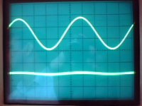
Top trace: Oscillator output at 5 V / div
Bottom trace: Sample and Hold capacitor C52 (increased to 10 nF) 5 mV / div
Thanks for the suggestion of looking at the August 1980 issue of the HP Journal for the description of the 8903 analyzer.
Thanks also for the Oscilloscope waveform and spectrum analysis plots. The THD that you are achieving is impressive.
I have now set the circuit up again so can take some more detailed measurements of the control voltage ripple.
Measuring at the Loop error header, component reference CON6 pin 1.
The Loop gain was adjusted using VR2 to give 0 V error at 1 kHz.
At the Oscillator Frequency = 100 Hz, control voltage ripple 1 mV peak to peak.
1 kHz, 1 mV peak to peak ( -60 dBV). I believe that this is feedthrough via the switch (IC7) off capacitance.
10 kHz, 3 mV peak to peak.
25 kHz, 5 mV peak to peak.
100 kHz 30 mV peak to peak dropping to about 7 mV peak to peak when the PCB is lifted from the desk. This is partly due to the length of the sample period. I think that the 2 stage approach of a peak detector followed by a sample and hold is best. I didn't think of it.
The frequency control dual ganged potentiometer is a Vishay Cermet 149 series. Part Number 14920F0GJSX13502KA, price from Farnell = £ 10.66 plus VAT.
I originally ordered a Vishay 148 series conductive plastic, greater drift with temperature but supposedly better resistance linearity (not matching of the gangs) for low distortion.
The frequency selection switch is an Elma 08-2104 form Farnell at £ 54.47 plus VAT.
Hi Benb I have used a PCB mounted switch which limits the number of poles to 2 (more are listed by Elma but are probably unavailable in small quantities). I agree another pole would be useful for the error amplifier control. The cost per switch contact is greater than the cost of a reed relay.
Top trace: Oscillator output at 5 V / div
Bottom trace: Sample and Hold capacitor C52 (increased to 10 nF) 5 mV / div
Attachments
Bottom trace: Sample and Hold capacitor C52 (increased to 10 nF) 5 mV / div
Hi PChi, your S&H output seems very clean indeed (although a spectral analysis could reveal quite a bit of HF content), but it's a little bit higher than optimal, too - it's likely to significantly raise the 2nd harmonic level in output signal. What's the signal level at the multplier output?
I'm trying to measure my T&H/S&H SVF generator, but - as expected - it seems to be a truly challenging task. More on this later.
Ciao,
L.
Last edited:
Hi L,
Thanks for the comments. The sample and hold output is clean because the low charge injection analogue switch, the Analog Devices ADG1221, is good though the 10 pin Mini Small Outline Package with a 0.5 mm pin pitch is a challenge to hand solder.
The multiplier output signal level varies from about:-
Frequency = 10 Hz. Multiplier output amplitide at IC10 pin 14 = 50 mV peak to peak
1 kHz, 60 mV.
10 kHz, 6 V peak to peak
100 kHz, 2 V peak to peak
I think that the multiplier output level could be reduced at high frequencies by adjusting the extra loop gain compensation components that I have added.
I have ordered an E-MU 0204 sound card which you mentioned earlier which looks good. I will try the ARTA software when the sound card arrives.
Regards Paul
Saw this on eBay, don't know if it's old news to everyone but:
Ultra low distortion (<0.00005%) 1kHz sine generator assembled and tested PCB
From Latvia, US$51 shipped
Second and third harmonic levels
unloaded or loaded 600ohm < 0.5 ppm ( < 0.00005%)
Output frequency 1kHz +/- 1%
Unloaded output voltage level 300mV - 2.6V (RMS)
Output impedance 600 ohm
External power supply DC voltage/current 35V / 25mA
Dimensions (W x D x H) / Weight 60mm x 70mm (50mm - board) x 27mm / 20g
Ultra low distortion (<0.00005%) 1kHz sine generator assembled and tested PCB | eBay
(No connection with me, was looking for an inexpensive tunable low-distortion oscillator, thinking of Farnell LFM4).
Hello,
Good post. The specifications are impressive. My guess is that it is fixed frequency which influences the design because the loop gain can be trimmed at 1 kHz which means that the gain control circuit can be set to have little effect hence cause little distortion.
It's going to be difficult to verify the really low second and third harmonic distortion levels.
... My guess is that it is fixed frequency which influences the design because the loop gain can be trimmed at 1 kHz which means that the gain control circuit can be set to have little effect hence cause little distortion.
It's going to be difficult to verify the really low second and third harmonic distortion levels.
Thanks. Sorry if my post wasn't clear, it is definitely fixed frequency. I suppose the best that can readily be done is to check that the harmonics are buried in noise with the equipment available; no better is needed.
Responding to another post, whether I buy one or not, no, I'm not going to test it for you - I'm not in a position to do anything useful, sorry.
Many years ago I built a Linsley Hood low-distortion oscillator which worked very well (I'm a fan of thermistors), but can't find it now. People tended to build oscillators and see what amplitude they got - I worked out how to calculate the amplitude from the thermistor specification, something I've never see anywhere. I submitted it to Wireless World for publication; they published something with my graph and formulas, but described it as a new type of oscillator, and the information sank without trace except for one letter criticising me for claiming the oscillator was a new idea.
I used the oscillator to help with designing and building a very cheap distortion analyser with an unusual technique, working at zero frequency - much easier to get a bandwidth of a few Hertz than at higher frequency where you require crystal filters. I think it worked quite well; I took out a provisional patent for some of the techniques but never quite completed the project, deciding there was no market, or at any rate it wouldn't help me much in making a living. I have the prototype, but all paperwork, including circuit, has gone; I don't even know if I would remember how to use it. The idea came from a suggestion in M G Scroggie's Radio Laboratory Handbook. It did give readings, harmonic by harmonic, from the low-distortion oscillator - it was sensitive enough. Nowadays you'd probably do better with a good computer sound card and software to generate waves and analyse them.
I haven't touched any of this stuff for a very long time, and am completely out of it. For some reason I thought it would be nice to have a low-distortion variable-frequency oscillator when I couldn't find mine, but probably won't find one which is low-distortion at a price I can justify (for probable shelfware). I was toying with the idea of getting a mediocre Wien-bridge one with passive components and switches, and replace the active circuitry, but realistically I'd never get it done.
Given this cheap Latvian 1kHz PCB, I played with the idea that continuously variable frequency is not necessary for many purposes; it might make sense to buy, say, three, and modify two for other frequencies.
But really I'm here under false pretences; I'm not active in the field.
Thanks. Sorry if my post wasn't clear, it is definitely fixed frequency. I suppose the best that can readily be done is to check that the harmonics are buried in noise with the equipment available; no better is needed.
Thanks for the clarification abut it being fixed frequency.
I too had a circuit published in Electronics and Wireless World. It was for an Oscillator using Analogue Multipliers to generate Sine and Cosine Squared then summing to give a low ripple gain control voltage. I acknowledged the reference I copied the idea from. A few months later someone who no doubt completely innocently thought the idea was new had a letter published describing the concept. So much for an informed Editor.
I agree that a sound card is good for the variable frequency measurements. For really low distortion and noise a few fixed frequencies is probably adequate.
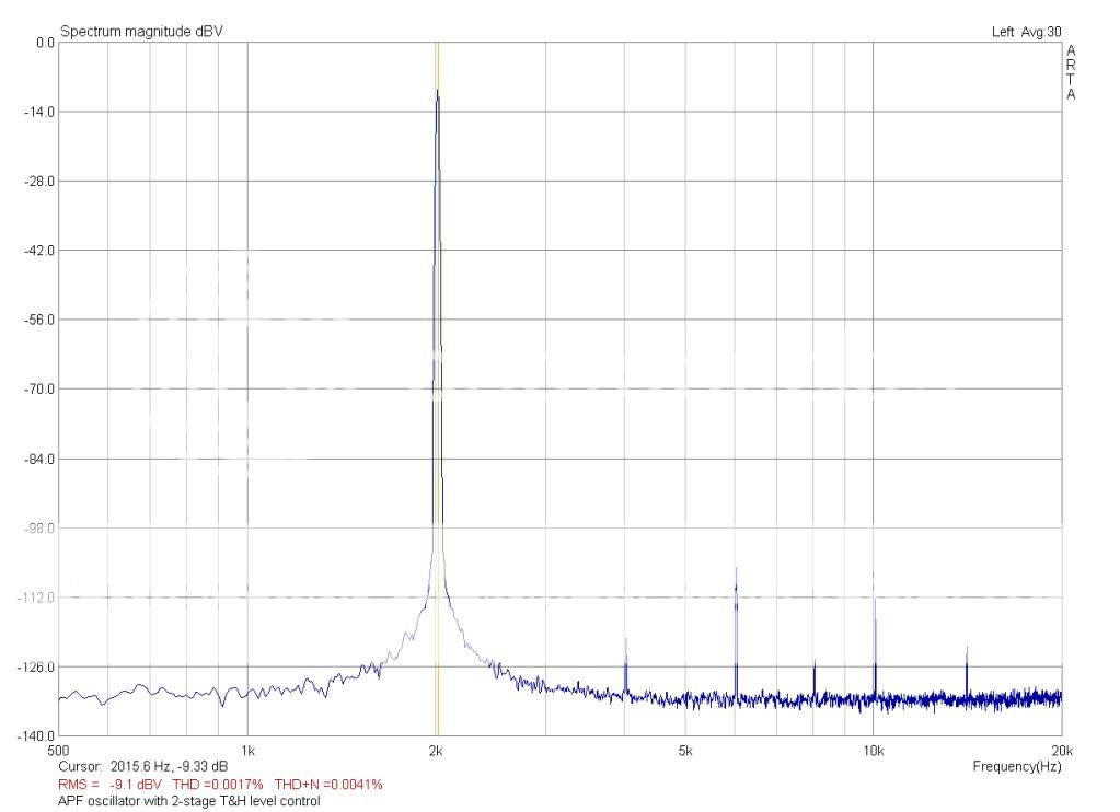
I recently built a version of the APF oscillator that was linked in the first post of this thread, and have gotten fairly good initial results for this simple circuit.
The level controller was redesigned. I used a couple of BJTs and a couple of JFETS to implement a simple two-stage track and hold. The BJTs form a differential pair that look at two phases of the quadrature signal and generate complementary control signals for the JFETS. The unused stage of the TL084 is used to buffer the first T&H section; and the LED driver stage subsumes the buffer for the final T&H stage.
Without tweaking, the oscillator is delivering the results shown below. These seem consistent with the results that coluke reported in post #7, though he approached the level control in a different way.
Cheers,
Curt
I recently built a version of the APF oscillator that was linked in the first post of this thread, and have gotten fairly good initial results for this simple circuit.
Those are impressive results.
I ordered a Creative E-MU 0204 USB Audio Interface but gave up after having to return a couple of wrongly delivered items. I need to find an alternative.
What sound card or external audio interface did you use to take the measurements?
What sound card or external audio interface did you use to take the measurements?
The measurement above was taken with an ESI Juli@ card. I also have an e-mu 0404PCI card. The two give comparable results, though their noise floors and spuriae are of course not identical.
I decided not to go the USB route as I was not sure that my lab PC could meet the transfer demands (it is rather old). I preferred to face the challenge of conducted and radiated noise associated with placing an analog interface inside the PC case
Cheers,
Curt
Thanks for the answers.
My first thought was to use an external interface connected via USB with possibly fewer noise issues. But after my failed attempt to buy one possibly I should follow your example and use an internal PCI card with no chance of any USB throughput issues.
Regards
Paul
- Home
- Design & Build
- Equipment & Tools
- Low-distortion Audio-range Oscillator