@richiem -- Thanks for your feedback and answers.
I'll not fit the AC coupling capacitor or the 49600 / 49710 combo.
I'll stay with the single ended output.
If someone designs a 16-bit ADC with a bandwidth of 500 kHz I would build one as well.
I have investigated the rapid rise in THD with frequency by both changing the level and using a passive Twin-T filter and I agree that it is caused by GBW limitation. The OPA134 operational amplifiers data sheet features list imply that they are good for 600 ohm loads but the typical performance curves show a marked increase in distortion when the load is reduced from 2 kohm to 600 ohm. Douglas Self's measurements in 'Small Signal Audio Design' confirm this. I kept the impedances low in the filter for low noise and dip a little below 600 ohms.
I built the Distortion Analyzer back in 1999 and used the OPA134 because they were in the original schematic from the Electronics and Wireless World article. I think that it's time to change them for some LME49710s which can drive 600 ohm with low distortion (according to the data sheet).
I think that it's time to change them for some LME49710s which can drive 600 ohm with low distortion (according to the data sheet).
Was it a design by Ian Hickman? If you are going to replace the OPA2134s with LME49710s then you will probably need to lower quite a bit resistor values both in the inverter stage and in the integrators - 2134's current noise density is about 3 orders of magnitude lower than the 49710's.
L.
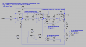
Thanks for your input. Yes is was a design by Ian Hickman published in the August 1999 edition of Electronics World. I modified the design but my memory is a little vague and my documentation is incomplete. The changes were:-Was it a design by Ian Hickman? If you are going to replace the OPA2134s with LME49710s then you will probably need to lower quite a bit resistor values both in the inverter stage and in the integrators - 2134's current noise density is about 3 orders of magnitude lower than the 49710's.
L.
I didn't include the Low Pass Filter. I was going to exceed the pin limit of the Vutrax PCB design software version I was using. Also the roll off is set for 20 kHz. I guess OK for measuring distortion at 1 kHz but not that much above.
I didn't use the residual amplifier design as I thought that it was lacking in bandwidth so I used 4 stages each using an OPA134 with switchable gain x1 or x10.
I used an Analog Devices AD536A rms to DC converter instead of the full wave rectifier and averaging circuit. I had the Analog Devices part on a board and I don't like just measuring the average of noise or distortion residual. Also full wave rectifier circuits can have bandwidth limitations.
I changed all the Notch Filter component values. I believe that there are some errors in the original schematic. R19 needs to be reduced for the notch filter to have unity gain for the residual. I believe that the values of R28 and R30 are transposed.
I reduced all the impedances by about 100 so the current noise density should be less of a problem but the OPA134 output drive capability is.
I also added a notch bypass switch, buffer and level set control.
I reduced all the impedances by about 100 so the current noise density should be less of a problem but the OPA134 output drive capability is.
I agree - if the driving impedances of the three stages are already in the kohm range the 49710's higher current noise density should not be a problem. I don't have Hickman's schematic at hand at the moment, but if I remember well it was a simple and clever design, with steep response despite of the pretty low filter Q.
L.
Last edited:
But the lowered Zs cause other, possibly serious, problems. Davada has observed the significant loss of open-loop gain due to even moderate output loading. A spec sheet statement about driving low-Z loads never points out this type of loss, which has big impacts on THD. Also, although the LME79XXX parts have many virtues, high input Z is not one of them, so that has to be taken into account, too, especially for integrators.
I think some form of compound circuit, or perhaps better, paralleling amps to increase drive and preserve open-loop gain, will turn out to be important for performance improvements.
I've not seen the Hickman analyzer article(s) -- are they available somewhere?
I think some form of compound circuit, or perhaps better, paralleling amps to increase drive and preserve open-loop gain, will turn out to be important for performance improvements.
I've not seen the Hickman analyzer article(s) -- are they available somewhere?
Could be a problem if the load was * very * low and you are looking for -120dB or lower THD throughout the whole audio band, of course, but - as far as i remember - hi-perf opamps are usually specified @ 2kohm load for THD, and @ 600 ohm, 2kohm and 10kohm load for OLG; Self in his 'Small signal audio design' checked a bunch of opamps for THD down to 500 ohm load @ 10Vrms out (i.e. true border-line operating conditions), and found very little (if any) loading-induced THD for quite a few of them (LM4562/LME49710, the venerable 5534 itself, AD 797, OPA627/637).
Anyway, going for such a low value of feedback resistors is pointless - I think something in the 10k range for the input inverter of an SVF notch, although not yet optimal from the noise point of view, could be a good trade-off between input impedance and noise itself; the 100 kohm Hickman used throughout his design are certainly appropriate for an OPA2134 (In ~ 3 fA/sqrt(Hz) @ 1kHz), but are way too high for a LME497XX (In ~ 1.6 pA/sqrt(Hz) @ 1 kHz).
Hickman's notch: I know I do have somewhere in my bookshelf a copy of the August 1999 EW issue containing the design, but I need some time to look for it - I'll let you know.
L.
Davada has observed the significant loss of open-loop gain due to even moderate output loading.
Oh, I missed this line - seems an interesting point: what do you mean by 'moderate'? And at what frequencies? I have a couple of experimental SVF generator based on LM318s and NE5534s working with 3.3 kohm resistors both in the feedback of the inverter stage and in the overall feedback from LP out to HP virtual ground, and this doesn't seem to have any sensible impact on THD even at 20Vpp out - at moderate frequencies, at least (THD is in the -120dBc); the SG505 by Tek (5534, 10Vpp or so max out, if I remember well, but it employs an output buffer) uses 5k42 and 2k15 in the same places, while AP1 (5534) goes for a little more confortable 5k and ~5k - it seems that output loads in khom order of magnitude (let's say higher than 2-3 kohms) aren't really going to affect THD performances of good opamps up to 20Vpp out or so (and LME497XX are way better than the good ol' 5534s...)
Ciao,
L.
The ability to characterize the point at which distortion increase is significant obviously depends on the ability to measure distortion accurately at extremely low levels. Pease's noise-gain method is the easiest to do; but "significance" is in the eye of the beholder. Is a distortion increase of 6dB above a very small amount significant?
I'm going to go out on a limb, since I haven't actually been making these measurements, and say that a reasonable loading where OLG starts to be affected in most amps is around 5kohm -- I'm just guessing; but the OLG decrease with frequency makes a single number impractical in any case. So, I guess I'm leaning toward techniques to isolate amps from loading effects and for extending GBW.
Why bother? Well, Cordell has shown that a lot can be learned about amplifiers by looking at their THD at 1kHz and at some higher frequency, like 20kHz. So having unimpeachable sources for 1kHz and higher -- for practical reasons I like 10kHz -- seems desirable. The old conventional wisdom about having measurement instruments 10X better than what's being measured may be too stringent, but it's a nice and convenient benchmark.
"Davada has observed the significant loss of open-loop gain due to even moderate output loading."
We should probably put this statement in contest here. It would be better if this read,
Davada has observed the significant loss of open loop gain due to even moderate loading in an undamped state variable filter/ocillator from a small number of op amp specimens.
Most of the datasheets I've seen that give distortion specs use a 1KHz standard and perform the distortion analysis using a unity gain inverter or unity gain follower circuit with exception to Nationals LME seires which used a special technique. But even with the special technique the test is normalized to unity and the distortion is inferred. Some manufactures are more honest then others so I take it all with a grain of salt.
In the case of an undamped SVO, with the damping components removed the Q and Fr gain becomes mathematically undefined and is limited by available open loop gain, amplifier bandwidth, component and board leakage. In terms of significance probably in that order.
Continued on next post.
Available open loop gain and bandwidth is not only required for the sections function but also for the filter,s loop stability.
With op amps under these conditions I have observed a significant rise in distortion from either internal or external loading of the op amps as well as lose of gain. even with moderate values of resistance in the the range of 1 to 5K ohms. But this must be taken into consideration with the existing loading from circuit components and operating conditions. In an undamped SV the Fr gain can be as high as 60dB or greater. That means a significant amount of available gain is used and there may not be a lot left to drive distortion down. So loading can become an issue.
There is more to this which I will get into at a later time.
What I said to Richiem was meant to be 'just something to watch out for' when designing and constructing oscillators, filters or other ultra low distortion op amp based instrumentation.
David.
Last edited:
Davada has observed the significant loss of open loop gain due to even moderate loading in an undamped state variable filter/ocillator from a small number of op amp specimens.
Of the same type (ie, 3 out of 10 OPAxxx tested in an undamped SVF ring showed a significant OLG loss when driving moderate loads), or of different types? Both interpretations could make sense, but they have completely different implications.
L.
Sorry, David -- I didn't mean to put words in your mouth, nor did I mean to leave any out; your observations just seemed especially germane to the discussion.
Not a problem Dick.
I thought it was important to point out the operating conditions. We are talking ppb distortion here.
Cheers,
David.
Last edited:
Of the same type (ie, 3 out of 10 OPAxxx tested in an undamped SVF ring showed a significant OLG loss when driving moderate loads), or of different types? Both interpretations could make sense, but they have completely different implications.
L.
Hi Coluke,
Out of same type with consistent results. Of course each type has it own magnitude of distortion. Some types will do better than others.
Everything intensifies with loading. Distortion on the power rails, ground return currents and EM. It is difficult to isolate the source of distortion at these levels and at such high gain.
David.
Hi Davada,
I've just done a few quick tests on the SVF generator I did mention in one of my last messages to investigate the effects of heavy loading. The generator is based on a ring of 5534s equipped with a 4-phase peak detector and a pair of paralleled AD633 as level controlling element; feedback from LP out to HP virtual ground is through a 3k3 resistor, and the inverting stage operates at unity gain, so 2 out of 3 5534s works over 3k3 (or a little less) load. Generator output is at LP output, and THD @ 1kHz, 20Vpp over 10k or so is a bit lower than -126dBc, or 0.00005%, and this is the reason why - honestly speaking - lowering it anymore wasn't really a big issue
") - I was more interested in trying to lower THD+N.
- I was more interested in trying to lower THD+N. Lowering the generator load down to 1.5 kohm * doubles * the output THD, but it seems to affect * only * the 2nd harmonic rising it to -120dBc, while the 3rd remains almost untouched at -130dBc - I can't see anything else down to -140dBc in the 4-20kHz range. Looking at the output of the multipliers confirms the 2nd harmonic rise, while both their output level and the oscillation frequnency * aren't affected at all * by the heavier load (and 1k5 @ 20Vpp is quite an heavy load for a poor old 5534...), which in turn means that the operating Q of the generator doesn't change (or changes by too a small amount to be detected).
Else I'm facing with some hard-to-find cancellation effects in my SVF notch (had no time to check THD rise with another notch based on a completely different topology), or test results are a little bit unclear, although they seem to indicate that the 5534 (which is indeed specified for 100V/mV OLG @ 20Vpp, RL>600 ohm) is a good performer on medium loads (or maybe a not-so-bad on heavy ones). Was the 5534 in the bunch of opamps you tested?
Here in the Bel Paese is late at night, so I'm not going to speculate at all on what I've found - I hope I'll have some more spare time during the weekend to recheck results and do some more testing, although I know that looking for something in the 1ppm range or below can be - and very often is - definitely frustrating...
Ciao,
L.
Hi Coluke,
Yes the 5524 was in the group.
The 1.5k sounds about right for a 20Vpp signal. What I found is it depends on the operating level and the operating loop gain, or ring if you prefer, of the filter as to what load the op amp can tolerate. As you have found the maximum load is quite a bit higher than what the data sheets claim for unity gain at 100% feedback. Evey op amp is a bit different in the absolute effective value.
I also found with loads down to 1K ohms or so that I could not operate the oscillator much above 7Vrms but with out a external loading could get 9Vrms. Again this varies with op amp used.
It really comes down to what one wants to achieve. Therefore there will be trade-offs with operating level, SNR and distortion.
There is the possibility of paralleling op amps to improve the same but I have not tried this. Apparently, paralleling op amps also increases bandwidth by nearly a factor of 2.
How are you determining Q of a running oscillator? Are you monitoring both the output of the oscillator and output of the multiplier to determine ratio change?
"Else I'm facing with some hard-to-find cancellation effects in my SVF notch (had no time to check THD rise with another notch based on a completely different topology),".
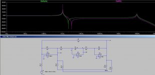
I was playing around in spice with an elliptic response by combining the HP and LP outputs. A 1:4 ratio lands the notch on the second H. You can choose any harmonic with other ratios. I haven't tried this. As you can see the LP response is lost and the higher order harmonics won't be suppressed. I suspect the noise will be higher as well.
One could follow this with an additional LP function but that means another section to tune.
Cheers,
David.
Yes the 5524 was in the group.
The 1.5k sounds about right for a 20Vpp signal. What I found is it depends on the operating level and the operating loop gain, or ring if you prefer, of the filter as to what load the op amp can tolerate. As you have found the maximum load is quite a bit higher than what the data sheets claim for unity gain at 100% feedback. Evey op amp is a bit different in the absolute effective value.
I also found with loads down to 1K ohms or so that I could not operate the oscillator much above 7Vrms but with out a external loading could get 9Vrms. Again this varies with op amp used.
It really comes down to what one wants to achieve. Therefore there will be trade-offs with operating level, SNR and distortion.
There is the possibility of paralleling op amps to improve the same but I have not tried this. Apparently, paralleling op amps also increases bandwidth by nearly a factor of 2.
How are you determining Q of a running oscillator? Are you monitoring both the output of the oscillator and output of the multiplier to determine ratio change?
"Else I'm facing with some hard-to-find cancellation effects in my SVF notch (had no time to check THD rise with another notch based on a completely different topology),".
I was playing around in spice with an elliptic response by combining the HP and LP outputs. A 1:4 ratio lands the notch on the second H. You can choose any harmonic with other ratios. I haven't tried this. As you can see the LP response is lost and the higher order harmonics won't be suppressed. I suspect the noise will be higher as well.
One could follow this with an additional LP function but that means another section to tune.
Cheers,
David.
Attachments
Hi Davada;
I've been thinking about this possibility for quite a long time, but never tried - it should be effective in reducing somewhat output noise, too.
Yes - @ 1kHz, 20Vpp on 10k load, multiplier output sits at about 120mVpp: taking into account the 10:1 decoupling factor, the operating Q seems to be as high as about 65dB (with WIMA red PP timing capacitors). A fairly simple and quick way to check this estimate can be made by grounding the multiplier VC input (which definitely stops the generator), and then finding out which value of resistance between BP output and HP virtual ground just restarts oscillations - with positive quadrature feedback via a 5.1Meg resistor oscillations build up in a few seconds, so running Q is * at least * 5.1Meg/3.3k, or 64dB - this is fairly consistent with the previous estimate, and happily accounts for the pretty low THD values I see.
Ciao,
L.
There is the possibility of paralleling op amps to improve the same but I have not tried this. Apparently, paralleling op amps also increases bandwidth by nearly a factor of 2.
I've been thinking about this possibility for quite a long time, but never tried - it should be effective in reducing somewhat output noise, too.
How are you determining Q of a running oscillator? Are you monitoring both the output of the oscillator and output of the multiplier to determine ratio change?
Yes - @ 1kHz, 20Vpp on 10k load, multiplier output sits at about 120mVpp: taking into account the 10:1 decoupling factor, the operating Q seems to be as high as about 65dB (with WIMA red PP timing capacitors). A fairly simple and quick way to check this estimate can be made by grounding the multiplier VC input (which definitely stops the generator), and then finding out which value of resistance between BP output and HP virtual ground just restarts oscillations - with positive quadrature feedback via a 5.1Meg resistor oscillations build up in a few seconds, so running Q is * at least * 5.1Meg/3.3k, or 64dB - this is fairly consistent with the previous estimate, and happily accounts for the pretty low THD values I see.
Ciao,
L.
Hi Coluke,
There perhaps an easier and certainly more accurate way to measure the gain at Fr.
Disconnect the multiplier output from the input to the filter, either use the same value input resistor or my preferred way is to use a resistor the same value as the feedback resistor in the inverter HP section. This way the test is calibrated for unity. But if you choose the former then simply calculate the attenuation factor. Then either using another oscillator fitted with an attenuator on the output, apply and adjust the input signal until the output of the filter is at operating level. Measure the input level from the oscillator and divide this into the filter's output level. Repeat at different frequencies and ranges.
My preferred method is to use ARTA's frequency response test in single mode using PN (periodic pink noise). ARTA does the heavy lifting for you by automatically calibrating this test.Therefore you can set the ARTA PN generator to any input level and it is normalized to 0dBu (relative level). This way you can examine all of the filter's frequency response.
You can then sweep the filter through all your selected frequencies and ranges.
You may be surprised at what you find. But then again maybe not. You will however know exactly what you are dealing with.
If you do this test let me know what you find.
It also works with any network tuned within the audio range, like notch filters for example. It's best to use the highest resolution in ARTA as the lower resolutions may give errors in amplitude reading with high Q circuits because low resolutions step past the peak or notch.
I used this to log the amplitude errors with richiem's Twin T filter. This way the error can be added to the measurement for correction.
One idea I discussed with Richiem is to make up a calibration file to level the errors.
But this would involve a calibration file for each test frequency as the error increases with increased frequency. One could dump the results of the test to a file and run a normalization macro, say in excel, on the data and use this for a calibration file.
Cheers,
David.
Last edited:
Hello,
After changing the OPA134s for LME49710s the total harmonic distortion (plus noise) at 25 kHz has dropped from 0.04 % to 0.02 % so a good result for me. No change at the lower frequencies. Interestingly the Texas Instruments Audio Guide (1Q 2012) doesn't include the OPA134 but I did buy them back in 1999.
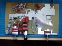
I had some trouble with the physical layout of the components so I am not keen to make any more modifications to the Distortion Analyzer in it's current physical implementation (The air turned blue when wires fell off and dealing with a DIY 'manufactured' double sided PCB without plated through holes tested my patience).
Thanks to davada for attaching the pictures and I admire the thd results achieved by coluke.
I think that I need to modify the design and produce a new board for the Distortion Analyzer with PCB mounted switches so it's possible to make changes relatively easily.
I have attached a picture of what I have ended up with for the Distortion Analyzer. Some of the component choices were dictated what what bits I had so it's in no way optimised.
After changing the OPA134s for LME49710s the total harmonic distortion (plus noise) at 25 kHz has dropped from 0.04 % to 0.02 % so a good result for me. No change at the lower frequencies. Interestingly the Texas Instruments Audio Guide (1Q 2012) doesn't include the OPA134 but I did buy them back in 1999.
I had some trouble with the physical layout of the components so I am not keen to make any more modifications to the Distortion Analyzer in it's current physical implementation (The air turned blue when wires fell off and dealing with a DIY 'manufactured' double sided PCB without plated through holes tested my patience).
Thanks to davada for attaching the pictures and I admire the thd results achieved by coluke.
I think that I need to modify the design and produce a new board for the Distortion Analyzer with PCB mounted switches so it's possible to make changes relatively easily.
I have attached a picture of what I have ended up with for the Distortion Analyzer. Some of the component choices were dictated what what bits I had so it's in no way optimised.
Attachments
I believe that I have drifted some way from the original post:-
My specification and preliminary measurement results are:
12 Frequency ranges:-
10 - 20, 20 - 50, 50 - 100, 100 - 200, 200 - 500, 500 - 1k, 1k - 2k, 2k - 5k, 5k - 10k, 10k - 20k, 20k - 50k, 50k - 100k.
Level nominal 5 V rms
Amplitude flatness with frequency within +/- 0.5 dB
Distortion and noise, measurement bandwidth limited by the rms to DC converter (AD536A). Also limited by the notch filter.
100 to 250 Hz 0.002%
1 kHz to 2.5 kHz 0.003 %
10 kHz 0.01 %
25 kHz 0.02 %
So not great but at least all the components are on one PCB. I really need to produce a Rev 0.2 PCB to tidy up the changes and remove some of the excess features to make the PCB smaller.
I haven't mounted the stepped output attenuator, the amplitude control potentiometers or the output buffers and coupling capacitors.
Attachments
- Home
- Design & Build
- Equipment & Tools
- Low-distortion Audio-range Oscillator