Anyone have a source for really low tolerance capacitors? I can barely find any +/-1%. I looked into getting an LCR bridge to match my own, but heck those things are killer expensive now. I can't believe I used to have a GR 1650 bridge that was perfectly fine but sells for something like $800 now!?!?! Even that bridge was only good for +/-1%. I seriously doubt that the capacitance measuring feature on my DMM is worth a crap.
Old Tek Scope timebase plug-ins. Have typicallly 1% or better mylar timing caps. The 5000 series ought to go for a song nowadays.
Doc
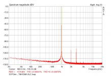
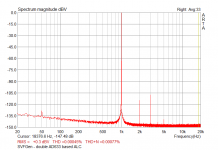
Just to clarify my previous post - I've attached couple of spectra from two of my low THD generator prototypes: the first one is based on a SVF ring of NE5534s, a T&H/S&H peak detector and a low cost analog multiplier (AD633) as level controlling element; the second one is a SVF ring too, but with venerable LM318s in place of NE5534s, a 4-phase peak detector and a couple of paralleled AD633 as level controller. Both generators are equipped with integrating ALC loop, and employs 5-10% red WIMA pp boxes (FKP) as timing capacitors. As you can see, both generator outperform the simple APF generator shown in the first post; they have lower THD, lower THD+N, and far better sideband performances. LM318 are definitely not known as ultra low thd opamps, still they are capable of remarkable performances - THD figures are probably entirely due to the EMU0204 used to capture the spectra: both generators are in 0.0001% (-120dBc) range or better - my notch says something near 0.00003% @1kHz, 20Vpp out.
The simple APF generator is very far from these figures, so building it with cost-no object parts doesn't make too much sense, IMHO.
Ciao,
L.
The simple APF generator is very far from these figures, so building it with cost-no object parts doesn't make too much sense, IMHO.
Ciao,
L.
Attachments
Hi all -- just dialed in to the thread, saw some references to my web pages, and got caught up.
I have yet to find a variable frequency oscillator better than the HP 239/339 (these are slightly different in their ALC circuits but have very similar performance), and these are about as simple as good oscillators get, with individual distortion products for 1kHz fundamental below the 0.0001% level.
It is impossible to evaluate distortion of an oscillator whose THD is lower than the THD of your sound card (or THD analyzer). The HP 331 series, for example, has a floor of about 0.01% in the mid-band; the HP339 has a floor of about 0.001%. The EMU 0202 or 0204 line inputs have a residual of about 0.0002% or so at 1VRMS at 1kHz. So if your oscillator is better than these, you won't know it.
My solution is to use an active notch filter that reduces the level of the fundamental without attenuating the harmonics. 60dB attenuation of the oscillator fundamental seems to be enough to increase the dynamic range of my EMU 0204 enough to allow measuring harmonics down in the 0.00003% and lower, with the noise floor as the limit. I generally tune for 80dB fundamental suppression, which is easy with the filter I built.
As Davada mentioned, I'm away from home for an extended period, so have made no progress on the IG-18 conversion to the HP 239 circuit. This is potentially the easiest way to get to very low levels of THD -- lower than 0.001% THD+noise.
I agree that it is likely that a SV (bi-quad) design is overall the best, IF the ALC issues can be solved or improved. I don't know how good the Jim Williams Wien bridge design can be -- I think that ALC issues are it's limit, if really good opamps are used, such as the LT1468. BTW, don't try to put a level control ahead of the LT1010 -- it's output drives the ALC circuit, putting it an an overall loop, so another output amp driven from the 1010 input should be used instead for a level controlled stage.
See my web page at Home -- article index and click the link to Active Twin-T Notch Filter to read about the details. Please note that the circuit drawing does not show the bypass switch for setting the input reference level -- that's a single-pole switch that connects to the input jack and to the U1 amp input. Closed, the switch takes the filter out of the circuit; open, the filter is in the circuit and can be tuned.
More Variable Frequency Oscillator thoughts
Hello,
My opinion is that I agree with Ciao that the way to go is a Sample and Hold or peak detector which theoretically eliminates modulation of signal by the amplitude control. The idea has been well proven.
I read years ago that the Radford Audio Oscillators used this technique.
The Hewlett Packard HP239A uses a peak detector.
The Black Star Audio Oscillator used something similar.
Another opinion of mine is that Ciao is correct that an Analog Multiplier is the most linear gain control element. Cyril Bateman used an SSM2018P. I have tried out an Analog Devices AD534 because I had one. I have a Texas Instruments MPY634 which I plan to use on the PCB that I am designing.
A couple of other thoughts are that I suspect that the low distortion of the HP339 relies on the well matched switched components to keep the gain variations low hence the voltage across the gain controlling FET low hence distortion low. The Black Star used a well matched dual gang potentiometer. Also I have always had problems stabilizing variable frequency integrator based, state variable, designs in the past so have chosen a phase shift arrangement.
I agree that Robert Cordell's Oscillator in the THD Analyzer is good but it is limited to switched frequencies. I have found that a variable frequency Audio Oscillator useful for testing where a loudspeaker low frequency cut off point is, checking loudspeaker drive units and crossover frequencies so low distortion isn't really required.
I think that the various Jim Williams designs are good but the ones that I have seen are fixed frequency.
@PChi -- when we're playing in the 1 part per million arena, I've learned to not take anything for granted. No ALC scheme involving rectification (or frequency multiplication) is totally without some distortion contribution. Heavy filtering leads ultimately to stability issues or unacceptably long settling times. Of course, smart designers will find clever solutions. Fluke resorted to quadrature rectification in their high-precision calibrators (5720) which allowed better filtering for a given loop time constant. As you note, the HP 239/339 use a half-wave peak detector and an integrator with adjustable Tau to provide drive to the JFET ALC element. And as Bob Cordell noted, the AC signalsat the ALC JFET's gate and drain need to be *very* small for lowest distortion.
For anyone who wants low THD from an oscillator (0.001% or less), but is not trying to milk mice, then the HP 239 circuit is a winner all around. Although it has switched frequency selection, it also has a vernier to allow tuning between the steps. It has a low parts count, and is easy to recreate, as I hope to show later this year, with IG-18 #3 (see my site).
I look forward to seeing some results for the design you all are working on here, and I offer to make some detailed measurements for anyone who wants to send me their unit, once I get back to my bench.
Hi all -- just dialed in to the thread, saw some references to my web pages, and got caught up.
I have yet to find a variable frequency oscillator better than the HP 239/339 (these are slightly different in their ALC circuits but have very similar performance), and these are about as simple as good oscillators get, with individual distortion products for 1kHz fundamental below the 0.0001% level.
It is impossible to evaluate distortion of an oscillator whose THD is lower than the THD of your sound card (or THD analyzer). The HP 331 series, for example, has a floor of about 0.01% in the mid-band; the HP339 has a floor of about 0.001%. The EMU 0202 or 0204 line inputs have a residual of about 0.0002% or so at 1VRMS at 1kHz. So if your oscillator is better than these, you won't know it.
My solution is to use an active notch filter that reduces the level of the fundamental without attenuating the harmonics. 60dB attenuation of the oscillator fundamental seems to be enough to increase the dynamic range of my EMU 0204 enough to allow measuring harmonics down in the 0.00003% and lower, with the noise floor as the limit. I generally tune for 80dB fundamental suppression, which is easy with the filter I built.
As Davada mentioned, I'm away from home for an extended period, so have made no progress on the IG-18 conversion to the HP 239 circuit. This is potentially the easiest way to get to very low levels of THD -- lower than 0.001% THD+noise.
I agree that it is likely that a SV (bi-quad) design is overall the best, IF the ALC issues can be solved or improved. I don't know how good the Jim Williams Wien bridge design can be -- I think that ALC issues are it's limit, if really good opamps are used, such as the LT1468. BTW, don't try to put a level control ahead of the LT1010 -- it's output drives the ALC circuit, putting it an an overall loop, so another output amp driven from the 1010 input should be used instead for a level controlled stage.
See my web page at Home -- article index and click the link to Active Twin-T Notch Filter to read about the details. Please note that the circuit drawing does not show the bypass switch for setting the input reference level -- that's a single-pole switch that connects to the input jack and to the U1 amp input. Closed, the switch takes the filter out of the circuit; open, the filter is in the circuit and can be tuned.
A couple of thoughts/observations here.
First, as with any THD measurements, the oscillator THD performance may very well not be as good at higher frequencies like 20 kHz as at 1 kHz. Unfortunately, most sound cards do not capture the spectra of many of the harmonics of 20kHz because of their limited sample rate.
I have an HP339 and have measured its oscillator THD with my own THD analyzer (which has a floor of less than 0.001% at 20 kHz, lower at 1 kHz), and have not really been impressed by the THD performance of the 339, so I'm surprized at your comments about it being really good (if I read you right).
The issue of the AGC element's distortion is always an interesting one. The tradeoff between using JFETs (which I used) and analog multipliers is always an interesting one. Keep in mind it comes down to a signal to noise ratio versus distortion issue. The analog multiplier is often capable of less distortion at a given operating level, but it often generates more noise than a JFET-based agc circuit. In my oscillator, I am able to operate the JFET at a very low signal level because the noise of the circuit can be kept low. Also bear in mind that the necessary amount of control correction range comes in. If you need a large correction range, you will have to operate the agc element at a higher level or suffer more noise from it. Designing an SVF osillator carefully so that it does not need a large agc correction range can be very helpful in reducing the distortion and/or noise introduced by the agc element and/or the amplitude detector.
Finally, when using a JFET agc element, it is important to use the feedback distortion correction circuit where approximately 50% of the drain signal is fed back to the gate, as used in my THD analyzer oscillator. For best results, the exact percentage of feedback for this should be trimmed for lowest distortion (assuming you can measure it!). This trim I did not do in my original design, but have incorporated it since. Note also that you can get a picture of the distortion contribution from the agc detector and agc element by looking at the output of the agc correction element, which will have a higher level of distortion than at the oscillator output because only a fraction of this signal is fed into the SVF for correction.
It also matters what kind of JFET you are using for the agc element. The one I chose for my oscillator was not by accident. It had a high threshold voltage and a fairly low Rds_on. Many ordinary JFETs will not perform as well.
It is also always interesting to look at which function is creating the most distortion: the agc element or the (rectifier) control circuit that generates the agc control signal. Looking at the harmonic structure of the THD can sometimes help sort this out. It is not always correct to just assume up front that the amplitude detector is the dominant source of distortion in the oscillator, especially if its filter circuit is switched in accordance with the frequency range being used, as the one in my THD analyzer is. This also relates to oscillator settling time, which is more often an issue at lower frequencies. BTW, for this reason, one should always characterize the distortion of the oscillator at the lowest frequency as well. Some HP oscillators actually had a low-distortion switch that traded distortion and settling time.
Cheers,
Bob
@Bob Cordell -- Hi Bob, thanks for the comments. I do think the HP 239/339 oscillators are very good, especially at mid-band and especially when the JFET feedback is tweaked. Unfortunately, the JFET feedback needs to be optimized for each frequency to get best 2nd H rejection -- which turns out to be true for your oscillator as well. This creates some problems...
I've compared the 239/339 to your oscillator, which I built, incorporating a JFET feedback trim, and to a KH 4500, which I picked up cheap off eBay and tweaked a bit (not the lowest THD when compared to a KH 4402B), and also to an LED/CdS controlled Wien-Bridge unit I built, similar to the Williams design. I have not had a Tek SG505 (phase-shift) to measure, nor the KH 4402B (bridged-t), both of which are considered to be very good, nor have I been able to evaluate an AP oscillator (SVF)/analyzer.
The goodness of the 239/339 design becomes apparent when you get rid of the fundamental and then use a spectrum analyzer to view the results. In my case I've recently used an EMU 0204 USB sound device to feed my PC running the ARTA analysis suite. The noise floor of the 0204 is pretty decent and the measurement BW, while not all I desire or need, is about 90kHz at 192kHz fs, albeit with a noise floor that rises significantly above 30kHz.
I fully agree that the higher frequency THD is not as good, but is still quite good compared to other units I've been able to test. I would love to have a hardware spectrum analyzer with a 1MHz BW and large dynamic range, preferably >90dB. But I'm doing what I can with the less expensive tools I have -- so far, so good.
My friend Davada has been looking at a novel control circuit, one which has the distinct advantage of not needing rectification of the control signal; I'll let him post about his work when he's ready.
As you so correctly point out, the trick is to not need a large dynamic range in the control element -- the less needed the better.
I now doubt that any active-filter auto-tuning THD analyzer, such as the HP 339, 8903, etc, has sufficiently low intrinsic THD to give a good picture of oscillator performance. But an Active Twin-T filter and a good spectrum analyzer can definitely do the job -- in my case, for mid-band audio frequency signals up to 10kHz or a bit more. Audio Precision seemed to think this filter-spectrum analyzer topology was best too.
@Bob Cordell -- Hi Bob, thanks for the comments. I do think the HP 239/339 oscillators are very good, especially at mid-band and especially when the JFET feedback is tweaked. Unfortunately, the JFET feedback needs to be optimized for each frequency to get best 2nd H rejection -- which turns out to be true for your oscillator as well. This creates some problems...
I've compared the 239/339 to your oscillator, which I built, incorporating a JFET feedback trim, and to a KH 4500, which I picked up cheap off eBay and tweaked a bit (not the lowest THD when compared to a KH 4402B), and also to an LED/CdS controlled Wien-Bridge unit I built, similar to the Williams design. I have not had a Tek SG505 (phase-shift) to measure, nor the KH 4402B (bridged-t), both of which are considered to be very good, nor have I been able to evaluate an AP oscillator (SVF)/analyzer.
The goodness of the 239/339 design becomes apparent when you get rid of the fundamental and then use a spectrum analyzer to view the results. In my case I've recently used an EMU 0204 USB sound device to feed my PC running the ARTA analysis suite. The noise floor of the 0204 is pretty decent and the measurement BW, while not all I desire or need, is about 90kHz at 192kHz fs, albeit with a noise floor that rises significantly above 30kHz.
I fully agree that the higher frequency THD is not as good, but is still quite good compared to other units I've been able to test. I would love to have a hardware spectrum analyzer with a 1MHz BW and large dynamic range, preferably >90dB. But I'm doing what I can with the less expensive tools I have -- so far, so good.
My friend Davada has been looking at a novel control circuit, one which has the distinct advantage of not needing rectification of the control signal; I'll let him post about his work when he's ready.
As you so correctly point out, the trick is to not need a large dynamic range in the control element -- the less needed the better.
I now doubt that any active-filter auto-tuning THD analyzer, such as the HP 339, 8903, etc, has sufficiently low intrinsic THD to give a good picture of oscillator performance. But an Active Twin-T filter and a good spectrum analyzer can definitely do the job -- in my case, for mid-band audio frequency signals up to 10kHz or a bit more. Audio Precision seemed to think this filter-spectrum analyzer topology was best too.
Hi richiem,
We think a lot alike. I've been using active twin-T filters for over 30 years. I've always loved twin-T's. In fact, before I built my THD analyzer, I measured THD at 1 kHz and 20 kHz with a pair of frequency-dedicated twin T filters with feedback. When last year I did some tweaking of my THD analyzer, I also used twin-Ts to look at oscillator distortion. As you correctly point out, the analyzer section usually cannot be as good as the oscillator. That is definitely the case with my THD analyzer.
BTW, what is interesting, but which was hard for me to prove, is that phase noise in the system seems to set the floor in my now-tweaked analyzer (close-in noise sidebands about the fundamental). It is not THD or flat noise in the SVF notch circuitry of the analyzer. I used to think that ordinary circuit noise set my floor, but that appears not to be the case. These were very difficult things to sort out by measurement, so what I am saying may just be intelligent speculation. Actually, to be more precise, the SVF notch filter in the analyzer is ultimately formed by a subtraction circuit, and any phase jitter or other close-in spectral noise near the fundamental impairs the notch.
Looking with a spectrum analyzer at the residual from my THD analyzer when it is driven by its own oscillator, the signal energy is dominated by fundamental and close-in sidebands, not flat noise or harmonic spectral lines. Looking at the same residual on a capture with a DSO shows that the phase of what little there is of the fundamental is all over the place, so it is not just an imperfect static tuning null.
At one point I thought I had some 1/f noise in my tuning control loops, but I could not find it and or reduce it. Of course, even ordinary circuit noise can be magnified about the fundamental in an SVF.
I probably could have learned more about it by doing lots of experiments, some involving an active twin-T, but the whole thing began to become a time sink.
Life for me would not be as good without my trusty old HP3580A analog spectrum analyzer, although unfortunately it only goes to 50 kHz and only has 85dB dynamic range (that's why twint-Ts or my distortion magnifier in front of it are very helpful).
Interestingly, I found that substituting modern LM4562s for the 5534s in my analyzer did not reduce the floor. That was a bit of a surprize. For its age, at least for instrumentation, the old 5534 is remarkable in distortion performance.
BTW, maybe I read you wrong, but the Tek SG 505, designed by Bruce Hofer before he helped found AP, is definitely an SVF oscillator. There are many aspects of the AP1 that are very similar to my THD analyzer. Bruce Hofer, Rich Cabot and I became good friends while they were still at Tek.
Cheers,
Bob
Hi richiem,
...
Interestingly, I found that substituting modern LM4562s for the 5534s in my analyzer did not reduce the floor. That was a bit of a surprize. For its age, at least for instrumentation, the old 5534 is remarkable in distortion performance.
BTW, maybe I read you wrong, but the Tek SG 505, designed by Bruce Hofer before he helped found AP, is definitely an SVF oscillator.
...
Cheers,
Bob
They are still among the best, and TI/BB seem not to have made them worse than the few old Signetics parts I still have. These days, I'm tending to use the LT1468 (or OPA134) unless the source Z is very low -- then the LME49710 looks pretty good.
You re right, the SG505 is an SV unit -- I'm not sure what unit I was thinking of.
It seems whatever filter is used, that everything else being equal, filter Q doesn't seem to matter in oscillator goodness -- rather it seems that overall maximum circuit gain (and GBW at higher freq's) is the determining factor -- and I'm sure that's no surprise to you. Someone here mentioned the need to control circuit gain vs frequency, and I'm guessing that controlling integrator Tau in the ALC is an important part of that.
Hello Richiem,
Thanks for your inputs and for your offer of detailed measurements. I'm taking nothing for granted until I have managed to put something together. I'm not claiming that I will be able to achieve 0.001 % or less just that I have taken a (very) slightly different approach. Certainly the HP239A circuit is good.
Also thanks for Bob Cordell's inputs and for his book 'Designing Audio Power Amplifiers' which was most interesting and money well spent.
I used to think that ordinary circuit noise set my floor, but that appears not to be the case.
Just as a side note: It is important to understand that the noise gain of the opamps in the oscillator becomes very high near the oscillation frequency. This results in a noise floor which looks similar to a jitter source with 1/f spectrum.
At one point I thought I had some 1/f noise in my tuning control loops, but I could not find it and or reduce it.
The demodulators look like a prime suspect. Most auto-tuning notch filters I've analyzed used switching demodulators which might be better with this respect (but are sensitive to harmonics, so might not null as nicely without further precautions).
Samuel
I thought that I would revive this thread because I now have a PCB up and running using the Texas Instruments / National Semiconductor LME49990 in a phase shift based circuit.
The sample and hold amplitude circuit works OK after I had some fun with the control loop. I didn't find it easy to get the loop to behave over the Oscillator frequency range of 10 Hz to 100 kHz.
The gain control works OK with the multiplier output attenuated by 100 which minimizes the noise contribution.
I am now at the distortion measurement stage. Performance is OK at low frequency 0.002 % at 100 Hz, 250 Hz and 1 kHz. But distortion rises rapidly when the frequency is increased above that, 0.003 % at 2.5 kHz. 0.01 % at 10 kHz and 0.04 % at 25 kHz.
It appears that the main problem is the Distortion Analyzer but it isn't easy to modify it the way I 'designed' and constructed it with capacitors soldered directly between the back of the rotary switches and the PCB relying on the case to hold them apart.
A nice readily available easy to build distortion analyzer design would be useful.
I haven't populated the PCB with the output attenuator and buffer because I am waiting until I am satisfied with the Oscillator.
I didn't choose a balanced output driver because I intend to use a bench power supply with an isolated output so the the output ground can float.
I have AC coupled the output with a physically massive 40 uF Polypropylene capacitor and am regretting the choice. The HP239A has a DC coupled output.
Has anyone any comments on what they would choose? AC coupled or DC? Single ended or differential?
I also went for a low impedance output using a National Semiconductor LME49600 buffer with LME49710 which I now think was excessive. The HP239A has a 600 ohm output impedance which I don't like but it does save on a buffer amplifier.
@PChi -- No need for AC coupling if the buffer has even fair DC stability -- *and* if the instrument or circuit being driven doesn't try to push DC back into the buffer. My opinion is that the 49600/49710 combo will raise THD -- others may have different opinions.
Balanced output is good if you work with professional audio gear, otherwise it's not needed or helpful. But I have found that being able to lift circuit ground off the chassis ground is very helpful. I have two oscillators that allow this -- an HP 239A and a K-H 4500, and it's been quite useful.
No conventional THD analyzer will show you the true distortion of the oscillator, which makes a low-noise active filter (like a Twin-T) and spectrum analyzer combination the best way to look at distortion. Of course hardware spectrum analyzers aren't cheap, but they are needed to see products of fundamentals above 20kHz. Software analyzers are cheap and effective up to 18kHz or so with a good audio ADC. I'm waiting for someone to do a DIY 16-bit ADC system that has a bandwidth of 500kHz (fs = 1MHz) and low noise here on the Forum... I'm not up to it myself.
As to the rapid rise in THD above a few kHz, this is almost surely due to the GBW limitation of the oscillator amp and the resulting loss of open-loop gain.
I have two IG18's from hamfests, they're barely operational, and I decided not to try to fool with them. I recall there was two articles from the first decade of Audio Amateur that describe improvements for lower distortion.Depends on what low distortion is...you can pick up a Heath IG18 (or the later IG5218) on eBay for under $50. Richiem on this forum has reported on upgrade to improve the performance substantially. Since the expensive parts are the case, multiple rotary selectors & decading components, this is a reasonable way to get there.
There was this group buy that was a great deal, but it looks dead at the moment, maybe you can post there and start it up again:I need to buy some 8 position SOIC to DIP adapters. I found a few in different places.
http://www.diyaudio.com/forums/group-buys/166811-group-buy-so08-dil08-adapter-adp0r0.html
I've seen this before, in Jung's "Audio Op Amp" book, and it was mentioned for power amps somewhere in the "Sound Quality Vs. Measurements" thread (the circuit/technique has a name, but I forget). Instead of going through an op amp, the input and output of an inverting amp are resistively mixed, making the whole thing passive (except for amplification of the resulting distortion components). There's R-C additions to the resistors to compensate for phase shift in the amp as well.I have an idea for making a distortion analyzer. It's not an entirely new idea though. I'm still reading about different techniques for measuring distortion. My idea, which came to me out of the blue, is to use a differential amplifier with really high CMRR and extremely low distortion as a difference amplifier. The oscillator output goes to one input and the output from the device under test goes to the other input after going through an attenuator. The DUT has to be non-inverting for this to work, and the phase error has to be nill as well. Basically, if you feed a common mode signal to a differential amplifier, what's left at the output is the junk that's the difference.
The problem that I see with the typical notch filter type of distortion analyzer is that amplifiers under test don't just amplify and distort the fundamental frequency from the oscillator, they also amplifier and distort every harmonic that the oscillator produces, as well as the noise and IM products. So, the output of the DUT becomes a mess of harmonics, noise and IM products that you can't separate out with a notch filter.
Anyway, I'm still working with this idea and it's clear to me that in order for my device to work I need a very low distortion oscillator and a differential amp with crazy high CMRR and vanishingly low distortion. The LME49990 seems to fit the bill so far. CMRR is 137 dB and distortion is 0.00001%.
Search for Bob Cordell's DMA (I hope I'm remembering that correctly) for a very good way of doing what Dirk is thinking about. Unfortunately, it doesn't work for measuring oscillators directly unless you have a VERY high performance oscillator to compare to (THD less than 100ppb?)...
- Home
- Design & Build
- Equipment & Tools
- Low-distortion Audio-range Oscillator